Search Criteria and Results
Within the Search Tool, you can construct filters using predicates or use the Find Similar option to carry out a search. After a search is carried out you can store the results in a filter or use them as a selection for further actions. A table view is available that simplifies working with a large collection of results.
-
In the Search Criteria panel, choose one of the
following options:
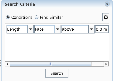
- To drive the Search Tool using predicates, select Conditions.
- To carry out a search that finds similar geometric entities, select Find Similar.
-
To set up and run a search using Conditions:
-
Click
 (Commit
Changes) to complete the search term.
(Commit
Changes) to complete the search term.
-
To add further search terms to the existing filter, click
 (Add
Item). You can combine multiple search terms together using
operators—see Filter Operators.
(Add
Item). You can combine multiple search terms together using
operators—see Filter Operators.
-
Click
-
To run a quick search using the Find Similar option:
In the following example, the blade of the drone highlighted in purple was selected.
 The image below shows the blades highlighted in yellow that the Search Tool found.
-
To construct a filter using the Find Similar option:
-
Select the Find Similar Mode options:
- Geometric Properties: Activates a search based on geometric similarity to entities within the selected entities. For example, if you selected Face for Input Type, the search is based on the area and perimeter of the selected face.
- Color: Activates a search based on the color of the selected entities.
- Search Tolerances: Allows you to specify a
tolerance value when comparing topologies or searching for entities. This option
is located at the top right side within the Search
Criteria box, see the image below. For more information, see Search Tool Reference.
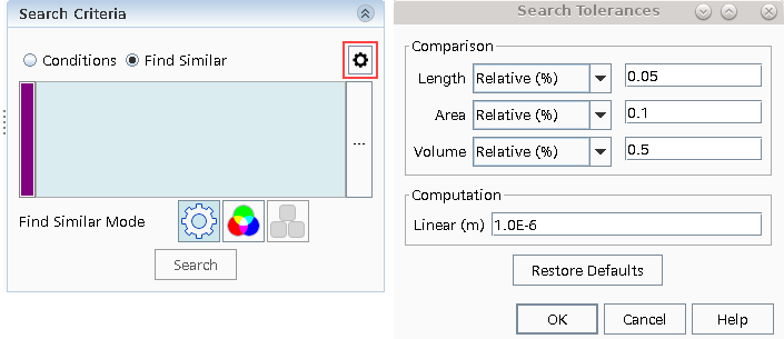
You can select these options individually or use them together.
-
Select the Find Similar Mode options:
The Results panel allows you to
customize the color of the results, navigate through them, and create a filter to store
them.
-
To navigate and store the results as a filter:
The search tool provides an optional table list view of results. The
tabular presentation simplifies the way you interact with and review a large collection of
results. While reviewing the results, you can use them as inputs to 3D-CAD features or apply
other interactions including visualization options.
-
To display the results in a table:
-
Next to Create, select
Table and click OK.
- By default, the result table appears between the 3D-CAD simulation
tree and the 3D-CAD View scene. The table is a
dockable panel and may be redocked elsewhere in the user interface.

If you hover the mouse pointer over a particular item in the table, a tool-tip appears displaying the complete description of the item.
- By default, the result table appears between the 3D-CAD simulation
tree and the 3D-CAD View scene. The table is a
dockable panel and may be redocked elsewhere in the user interface.
-
For items that you want to work with, in the selection column (second column),
activate their check boxes.
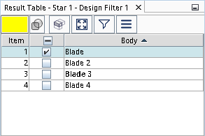
If you highlight multiple items in the table and activate or deactivate one of their checkboxes, all highlighted rows are similarly activated or deactivated. -
In cases where you have a large collection of results, you can use the
 (Show entity clusters in the table)
option to group connected items together.
The image below shows results from a clashing pairs search before and after using the cluster option.
(Show entity clusters in the table)
option to group connected items together.
The image below shows results from a clashing pairs search before and after using the cluster option. These clusters may then be used as inputs to 3D-CAD features. If items in the table are consumed by a feature operation (for example, deleted or united with other items), the word consumed is displayed in place of the item description.
 -
To use the selected items as inputs to 3D-CAD features, click
 (Activate feature menu) and choose the target feature.
After selecting Activate feature menu, the table is disabled until the selected feature is completed or cancelled. To close the feature menu, use <ESC> or click outside the menu.
(Activate feature menu) and choose the target feature.
After selecting Activate feature menu, the table is disabled until the selected feature is completed or cancelled. To close the feature menu, use <ESC> or click outside the menu.
-
Next to Create, select
Table and click OK.