Setting up the Fan Interfaces
Two fans drive the flow inside the PC case.
In this tutorial, you model the case fans using fan interfaces. A fan interface models the pressure rise through an axial fan as a function of local flow rates or velocity. A fan interface can only be used between regions that belong to the same fluid continuum. In this tutorial, the fan interfaces are located between Air Case and Air Inlet and between Air Case and Air Outlet.
Using parts-based interfaces and per-contact values, you can model multiple fans using a single interface. In this tutorial, you model two identical fans, each defined by a part contact, using a single interface.

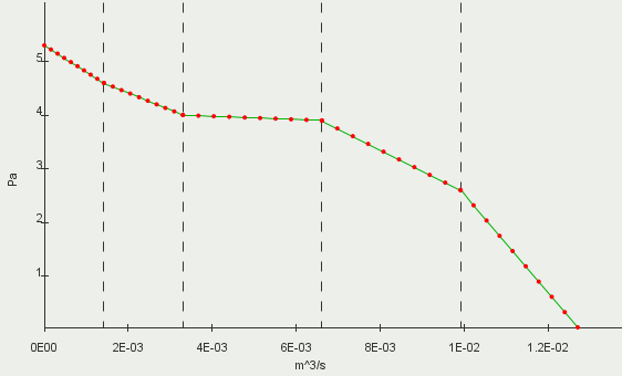
The polynomials that define the fan performance curve are:
Set up the fan interface:
- Expand the Interfaces node.
- Select the Case Fans node and set Type to Fan Interface.
-
Set
Allow Per-Contact Values to
True.
The Contact Subgroupings node is added to the Case Fans node.
-
Expand the
node.
The Subgroup 1 node contains the contacts for the inlet fan and outlet fan.
- Rename Subgroup 1 to Inlet Fan.
-
Right-click the
Subgrouping 1 node and select
New.
A new subgroup, Subgroup 1, is added to Subgrouping 1.
- Rename Subgroup 1 to Outlet Fan.
- Select Outlet Fan and set Objects to .
- Select the node and set Mode to Manual.
- Right-click Orientation and select, Reverse Contacts.
-
In the
Reverse Contacts dialog, expand the contacts folders.
Each contact has an icon with a direction arrow,
 , to indicate the orientation of the interface. For
Inlet Upstream/Inlet Downstream, the arrow indicates that the flow is moving from the upstream side of the interface to the downstream side of the interface, which is correct. For the
Outlet Downstream/Outlet Upstream contact, arrow indicates that the flow is moving from the downstream side of the interface to the upstream side of the interface, which is incorrect.
- To correct the orientation of the outlet fan interface, select the node and click OK.
- Select the node and set Curve Type to Polynomial.
- Expand the node.
-
Select the
Fan Curve Polynomial node and set
Specify by Part Subgroup to
True.
The By Contact Subgroup node appears within the Fan Curve Polynomial node.
- Expand the node.
-
Select the
Fan Curve Polynomial node and click
 next to the
Polynomial property.
-
In the
Fan Curve Polynomial dialog:
- Set the Operating Rotation Rate to 1200.0 rpm.
- Set the Data Rotation Rate to 800.0 rpm.
- Right-click the node and select Copy.
- Right-click the node and select Paste.
- Multi-select all the interfaces, except for the fan interface, and make sure that Type is set to Contact Interface.
- Save the simulation.