Visualizing the Mesh
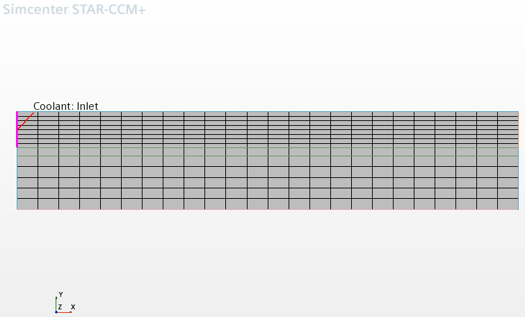
Create a mesh scene to view the mesh.
An axisymmetric mesh of the fuel pin, cladding, and coolant has been prepared for this analysis, so further meshing is not required. The boundary names and types are as defined in the imported mesh. View the mesh to examine these boundaries.
To visualize the mesh:
- Create a mesh scene.
The fuel pin is 1 m long in the X direction and 0.01 m in the Y direction. To visualize the scene with an improved aspect ratio, create a simple transform to stretch the domain in the Y direction:
- Right-click and select .
- Rename the newly created Simple Transform 1 node to Resize Domain.
- In the Properties window, set the Scale property to [1.0, 20.0, 1.0].
-
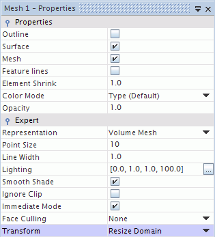
To apply this transform to the mesh scene, select and set its Transform expert property to
Resize Domain.

-
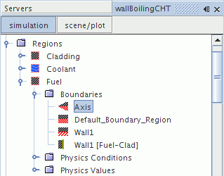
To examine the imported boundaries, expand the
node and select the
Axis node.

This boundary is highlighted in Mesh Scene 1.
-
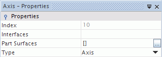
In the
Properties window, make sure that the
Type is set to
Axis.

-
Similarly, select the
node and observe which part is highlighted in the scene.

- Save the simulation.