Creating Phases and Selecting Phase Models
Create the phases and select the appropriate phase models.
The two phases flowing through the coolant section of vertical pipe are water and steam. These phases are defined by creating them under the Eulerian Phases model, and selecting the corresponding material properties.
To create the phases and select the phase models:
- In the Coolant continuum, right-click the node and create a phase.
- Rename the Phase 1 node to Liquid.
-
For the
Liquid phase, select the following models:
Group Box
Model
Enabled Models
Flow (Pre-selected)
Turbulent (Pre-selected)
Material
Liquid
Reynolds-Averaged Navier-Stokes (Selected automatically)
- Deactivate Auto-select recommended models.
-
Select the following models in order:
Group Box
Model
Reynolds-Averaged Turbulence
K-Epsilon Turbulence
K-Epsilon Turbulence Modelss
Standard K-Epsilon
Wall Distance (Selected automatically)
- Activate Auto-select recommended models.
-
Select the following models in order:
Group Box
Model
Enabled Models
High y+ Wall Treatment (Selected automatically)
Equation of State
Constant Density
Energy
Segregated Fluid Temperature
- Click Close.
- Rename the node to H2O (l).
Create the gas phase.
- Create a second phase and rename it to Vapor.
-
For the
Vapor phase, select the following models:
Group Box
Model
Enabled Models
Flow (Pre-selected)
Turbulent (Pre-selected)
Material
Gas
Reynolds-Averaged Navier-Stokes (Selected automatically)
- Deactivate Auto-select recommended models.
-
Select the following models in order:
Group Box
Model
Reynolds-Averaged Turbulence
K-Epsilon Turbulence
K-Epsilon Turbulence Models
Standard K-Epsilon
Wall Distance (Selected automatically)
- Activate Auto-select recommended models.
-
Select the following models in order:
Group Box
Model
Enabled Models
High y+ Wall Treatment (Selected automatically)
Equation of State
Constant Density
Energy
Segregated Fluid Temperature
- Click Close.
-
Rename the
node to
H2O (g).
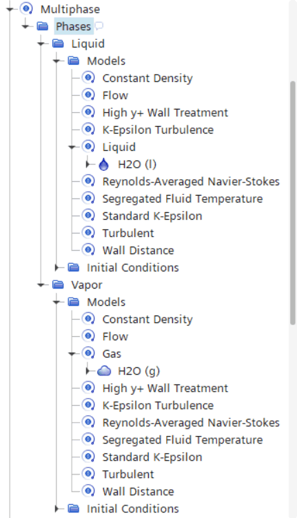
The Phases node appears as shown.
The material properties for each phase are now modified, starting with the water phase.
-
Edit the
node and set the following properties:
Node Property Setting Value 745.65 kg/m^3 Value 9.253E-5 Pa-s Value 1276100 J/kg Value 5310.0 J/kg-K Value 560.65 K Value 0.574 W/m-K
-
Edit the
node and set the following properties:
Node Property Setting Value 37.52 kg/m^3 Value 1.9034E-5 Pa-s Value 2770300 J/kg Value 5440 J/kg-K Value 560.65 K Value 0.06514 W/m-K - Save the simulation.