Offset Edges Mode
This mode allows you to offset the defined source edges onto the destination faces. These edges are imprinted onto the target faces to allow you to tailor the surface topology.
-
In the Global tools panel, click
 (Offset/Imprint
selected edges).
(Offset/Imprint
selected edges).
-
Select Offset Edges in the Edge Create
Mode option.
The following image shows the Offset/Imprint selected edges tool in Offset Edges mode.
The tool operates in three modes:
- Coordinate Offset—allows you to offset edges based on a relative coordinate offset value, for example projecting edges 2mm in the X direction. This mode works well for regular geometries (boxes and tubes) that conform to a coordinate system (laboratory, local Cartesian, local cylindrical, and local spherical). In this mode, the target faces can be defined anywhere in the part where the imprint is expected to occur.
- Projection Offset—allows you to project each source edge based on either the shortest distance between the source edges and destination faces, or a specified coordinate direction between the source and destination. This mode works well for topologies where the offset edges are a variable distance in space from the target faces. For this mode the source edges should not be part of the target faces.
- Geometry Offset—allows you to project each source edge based on the local vertex conditions. This mode works well for complex and organic topologies that don't necessarily conform to any coordinate system, such as the trailing edge of a propeller blade. The Geometry Offset mode has the distinct advantage of performing multiple projections in one operation since the projection direction is implied from the destination faces and not a single coordinate direction.
-
To select edges for the Source Edges and faces for
the Destination Faces, select a set of edges or
faces in the graphics window and click
 In the Graphics window, edges added to the Source Edges appear green, and the faces added to the Destination Faces appear red. You can repeat this action multiple times for different sets of edges or faces.
 -
You can remove edges or faces by selecting them in the display, and
clicking
 for
the source or destination.
for
the source or destination.
-
To remove all faces from the source or destination, click
 .
.
-
In the Offset/Imprint Edges Options
panel, define the Edge Offset Mode and the
respective properties:
- For the Coordinate Offset and Geometric Offset modes, set the Offset Distance to the distance by which to offset/imprint the edges.
- For the Projection Offset mode,
set the Projection Method and the
Projection Direction.
The Projection Direction is only required if the Projection Method is set to Specified Direction.
- In the Tolerance box, enter the edge imprint tolerance value (default 0.01 m).
-
If you want to control the projection of vertices, then choose one of the
options for Sample rate. See Sample Rate.
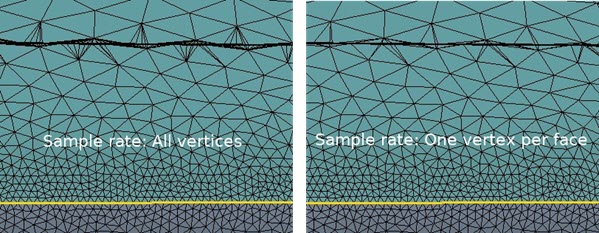
For good quality surfaces the default behavior (All Vertices) gives the most consistent results in terms of the continuity/smoothness of the projected edges. However, the other sample rates can be more appropriate depending on the local face quality and variation of triangle size from one face to the next. As more vertices are skipped, the chances of encountering inverted edges (those that cross over each other in the result) decreases.For complex geometries, some iteration can be required in order to get a good result, specifically by using different Sample rate options. The example below shows a comparison of the effect of the sample rate on a surface containing a remeshed tessellation that varies considerably from high to low gradient areas. Although both sample rates give a good projection result, the reduced triangulation on the imprint for the One vertex per face result makes it the better choice in this case—since the result contains less triangles without any significant loss in edge fidelity. This requires less clean up when used in the downstream meshers.
-
To flag edges as part curves, activate the Flag edges as
features option.
If you decide to flag the imprint edges as curves then a new part curve object is created for the part with the name "Surface Repair Offset Edges". All further curves created for that part re-use this part curve object. Once you exit repair, you can decide to rename the part curve object and/or split the curves up into smaller groups.
-
For the Geometry Offset mode, if you wish to remove
the inverted edge projections, set the Remove sharp
angles option to the desired value.
The Remove sharp angles option has a range of 0 to 5 iterations, with two or three iterations being required for the majority of topologies to remove the inverted edges. Inverted edge projections are a result of surface crawl paths crossing over each other. This typically occurs for topologies which contain highly curved convex type source edge definitions and poor quality starting triangles.
-
Once you have set the properties, to visualize the results of the initial
edge projection before executing the offset operation, click Preview
Offset..
This Preview Offset option is a useful option for complex geometries as it can save a lot of time when attempting to generate a result. It also allows you to verify if the input values are appropriate and runs all the pre-checks on the input subset requirements prior to the projection being performed.
- If you are not satisfied with the result from the preview, click Clear Preview and update the input settings before repeating the process.
-
To execute the operation, click Offset/Imprint Edges.
When complete, the Output window shows feedback from the operation.
 In some cases, during the preview and/or offset edge execution process, you may see a warning indicating that some vertices were skipped in the Output window, as shown below:
This warning indicates that a good projection result was not possible for the specified vertex so it was not included in the final projection result used for creating edges for the edge imprint. The general root cause for vertices being skipped is poor surface quality in the source/destination area. If only a small percentage of vertices are skipped then this is usually not a concern and good result can still be obtained. However, if the desired result is not achieved due to too many vertices being skipped then remesh the surface with a higher fidelity and try the projection again.Warning: Projection not possible for vertex 7900. Skipping this vertex.In some scenarios, you can encounter inverted edges. These edges are generally caused by source edges that have vertices too closely packed together relative to the overall triangle size. The target vector calculated from each neighbor vertex causes a new edge chain that turns on itself (inverted). An overall assessment is included at the end of the calculation for each chain. If the number of inversions is greater than 20% of the overall number of projected vertices, then the following warning appears:
In most cases this problem is not a concern and a good offset result can still be achieved. However, if a better offset is required then the surface should be remeshed or alternatively use a sample rate that uses less input vertices. In general the One vertex per face sample rate option is likely to give the least number of inverted edges.Warning: The inverted edge count is significant for this edge chain. The offset edge results may not be good. Improve the surface quality or try a different sample rate to improve the projection result.