Applying and Testing Constraints
Apply minimum constraints to allow for free thermal expansion.
When constraining a part for thermal-structural analysis, avoid applying constraints which are too restrictive and lead to unrealistic stress concentrations. In this tutorial, you apply constraints at three points on the manifold to prevent rigid body motion, while allowing free expansion of the solid structure.
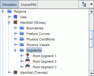
Create a point segment to constrain one point on the manifold in all degrees of freedom:
- Right-click the node and select .
-
Select the
node and set the following properties:
Node Property Setting Point Segment 1 Points Vertex 1 Type Constraint 
Method Fixed (default)
Define a segment to constrain the second point along two axes:
- Right-click the Segments node and select .
-
Select the
Point Segment 2 node and set the following properties:
Node Property Setting Point Segment 2 Points Vertex 2 Type Constraint 
Method Displacement 
Method Composite  Composite
Constrain X Deactivated Constrain Y Activated (default setting) Constrain Z Activated (default setting)
Define a segment to constrain the third vertex along y:
- Create another point segment.
-
Select the
Point Segment 3 node and set the following properties:
Node Property Setting Point Segment 3 Points Vertex 3 Type Constraint 
Method Displacement 
Method Composite  Composite
Constrain X Deactivated Constrain Y Activated (default setting) Constrain Z Deactivated 
In thermal strain analyses, it is important to define realistic constraints. A fixed condition on a surface segment can prevent thermal expansion and lead to unrealistic stress concentrations. To test your set of constraints, increase the temperature uniformly and run the analysis. The resulting stresses must be close to zero:
-
Edit the
node and set the following properties:
Node Property Setting Method Specified Method Constant Value 650 K
Freeze the flow and energy solvers and run the FE Stress solver for two iterations:
- Select the node and set Maximum Steps to 352.
- Expand the Solvers node.
- Multi-select the Wall Distance, EB K-Epsilon Turbulence, and K-Epsilon Turbulent Viscosity nodes and activate Solver Frozen.
- Select the Coupled Implicit solver and activate Freeze Flow.
-
Click
 (Run).
-
When the stopping criterion has been satisfied, open the
von Mises Stress scene and examine the stresses.
As the stresses are approximately zero, the applied constraints are not too restrictive.
- Save the simulation.