Projecting Vertices In A Coordinate System
The mode projects vertices to a single or double ordinate location in a given coordinate system.

This mode differs from the project to plane mode as projections to cylindrical and spherical planes are possible.
-
First select the
.
Selecting the coordinate system (, , or ) updates the Projection Ordinate(s) menu with the appropriate coordinate directions.
-
You can then select the
, and enter the ordinate values in the desired units. The dialog accepts negative values for the radial direction in a cylindrical system, which projects vertices in the opposite direction.
- The projection is performed when you click Project Vertices.
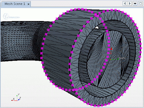
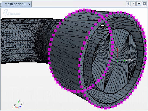
The following example projects vertices in the radial direction of a cylindrical system. The projection reduces the sleeve outer radius value to produce a thinner sleeve. This example uses a cylindrical coordinate system that is defined at the axis of the sleeve, where the radial axis points outwards.
-
Select the vertices on the outer surface:

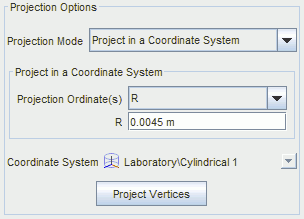
- Open the Project Vertices in-place panel, and select the mode.
-
Select the cylindrical system for the
Coordinate System, and enter the radial, R,
Projection Ordinate value.

-
The projection is performed when you click
Project Vertices.
The Graphics window displays the new result.

The tool maintains the original vertex selection, so you can repeat the process for different radial values.