Visualizing Free Surface in the Moving Part
To check for any air or paint trapped in the chassis during the dipping process, you create a scene that follows the motion of the chassis. The motion managed coordinate system Cartesian 1 allows you to do this.
- Create a new geometry scene.
- Rename the scene to ISO Surface.
- Delete the displayer Outline 1.
- Select the node of the ISO Surface scene and set Coordinate System to .
- Select the node and make sure Save to File is deactivated.
- Right-click the Derived Parts node and select .
-
In the Create
Isosurface dialog set the following properties:
Property Settings Input Parts Background, Overset Scalar Volume Fraction of Paint Isovalue 0.5 Display New Surface Displayer -
Click Create and then
Close.
A new Isosurface Surface 1 appears in the opened scene ISO Surface.
-
Select the Surface 1 node and set the following
properties:
Property Settings Opacity 0.4 Outline ✓ Surface ✓ -
Select the node and select the following parts:
-
In :
- ground
-
In :
- cavity
- chassis
-
- From the main simulation tree, select the node and drag it onto the scene ISO Surface.
-
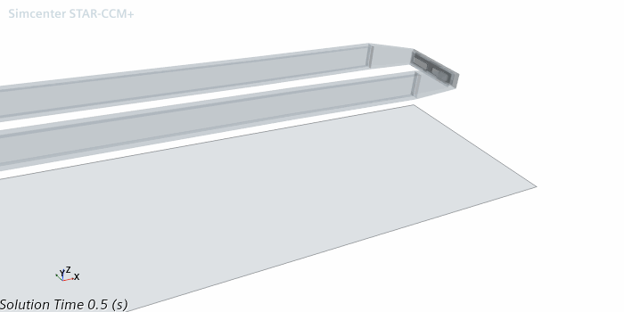
Adjust the view to capture the rear part of the chassis, where air is likely to
be trapped.
The defined visualization is shown below:
Create a solution history, .simh, file and use it
to store motion and coordinate system data along with selected solution data at
specified time intervals.
- Right-click the Solution Histories node and select New....
-
Save the solution history file as chassis.
Next to the new chassis node in the object tree, the red asterisk means that data is actively written to the file when the simulation runs. The Auto-record property controls this process.
-
To choose what data to write to the solution history file, and the frequency of
writing it, edit the node and set the following properties:
Node Property Setting chassis Auto-record Activated Inputs In :
- ground
In :
- cavity
- chassis
In Derived Parts:
- Isosurface
 Update
Trigger Time Step  Time-Step Frequency
Frequency 5 Note All motion and coordinate system data in the simulation is recorded in the simulation history file automatically. You do not need to select anything for motion or coordinate systems.