Defining the Trajectory Motion with Constrained Rotation
The motion path for the component passing through the tank was previously defined in a CSV (comma separated variable) file. After importing this file for the trajectory motion, you position the geometry in such a way that the location of the first contact point in the real scenario—for example the first hanging point of the rack on the skid, matches the first path point in the CSV table. The starting orientation of the moving region is kept unless you define an extra rotation.
There is no physical contact between the region and the trajectory. After setting up the trajectory motion, a translation is calculated based on the trajectory and assigned to the region after each time step. In the paint dipping case, a superposed rotation must also be defined to follow the orientation of the curved skid. That is, you add a constrained rotation for the motion in addition to the translation. The complete transformation is then applied to the chassis region. The paint dipping motion is illustrated below:

-
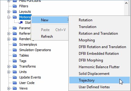
To define a trajectory motion:
-
To capture a certain part of a moving body in a post-processing scene, you
create a coordinate system managed by the trajectory motion and apply this
moving coordinate system in the View of the specific
scenes.
-
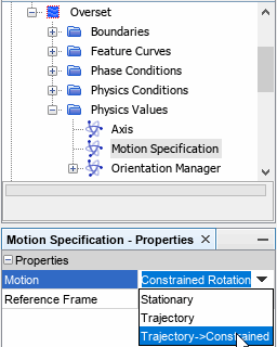
To complete motion setup with constrained rotation:

