Setting Up the Physics
As the simulation involves moving parts in real time the implicit unsteady solver is selected. The mixture of paint and air is solved as a multiphase flow applying the Volume of Fluid (VOF) model.
In the physics continuum you select the Adaptive Mesh model then activate free surface mesh refinement and overset mesh refinement. Additionally, you create a flat wave from the VOF waves model and use its field functions for initializing the VOF phases.
To select the physics models:
-
For the physics continuum,
, select the following models in order:
Group Box
Model
Space
Three Dimensional
Time
Implicit Unsteady
Material
Multiphase
Multiphase Interaction (Selected automatically)
Volume of Fluid (VOF)
Segregated Flow (Selected automatically)
Gradients (Selected automatically)
Viscous Regime
Turbulent
Reynolds-Averaged Navier-Stokes (Selected automatically)
K-Epsilon Turbulence
Realizable K-Epsilon Two-Layer (Selected automatically)
Wall Distance (Selected automatically)
Two-Layer All y+ Wall Treatment (Selected automatically)
Optional Models
Gravity
Adaptive Mesh
VOF Waves
VOF Wave Zone Distance (Selected automatically)
- Click Close.
-
To specify the model driven adaptive mesh criteria:
- Right-click the node and select .
- Right-click the Adaptive Mesh Criteria node and select .
- Use the default settings for the two refinement criteria.
-
To add two Eulerian phases:
Note Material properties of H2O are set as default when the liquid material is selected. To simplify the tutorial set-up, the material properties of water are kept. In a realistic paint dipping simulation, the correct material properties of the paint should be applied in the physics continuum. -
To create a VOF flat wave:
- Right-click the node and select .
- Select the Flat Vof Wave 1 node and set the Point On Water Level to [0,0,-1.92]m.
You obtain the following field functions to use as initialization and boundary condition settings: -
To set initial conditions, in the Physics 1 continuum,
edit the Initial Conditions node and set the following
properties:
Node Property Setting Pressure Method Field Function Scalar Function Velocity Method Field Function Vector Function Volume Fraction Method Composite 
Method Field Function Scalar Function 
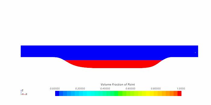
Method Field Function Scalar Function At the start of the simulation, the dipping tank is filled with paint to the depth of 2.08m.
-
To set the correct volume fraction condition on the pressure outlets:
- Save the simulation.