Contact Prevention
Contact Prevention avoids the merging of two or more part surfaces that are close to one another during surface wrapping.
This functionality is useful during meshing as it keeps certain surfaces separated, which would otherwise be amalgamated as one due to the surface mesh size settings.
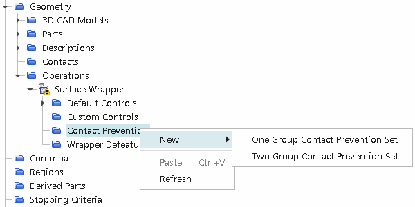
Two options are available:
- One Group Contact Prevention Set
- Two Group Contact Prevention Set
Once you have defined a contact prevention set, the following properties are available:
- Search Floor
- Enable Contact Prevention Set
- Using Parts and Shapes to limit contact prevention
In addition to common menu items, the right-click menu of a contact prevention set contains actions for:
- Interactively selecting surfaces within the set
- Specifically highlighting surfaces when default highlighting has been deactivated.
Empty contact prevention sets appear grayed out in the object tree and behave like deactivated sets. These empty sets are still considered active but do not have any effect on the mesh — the mesh pipeline continues normally. If you want to deactivate a particular contact prevention set, see Enable Contact Prevention Set.
One Group Contact Prevention
One Group Contact Prevention Set allows individual part surfaces to be grouped, such that each part surface forms a contact prevention with every other part surface grouped in the set.
-
Selecting
One Group Contact Prevention Set creates a node that is called
Contact Prevention 1.
The properties of this node are shown below for a parts-based meshing approach:
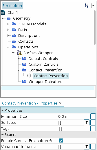
The part surfaces that form the contact prevention set can be selected using two different methods.
The first option uses the object selection dialog, which is accessible by clicking the ellipsis (...) next to Surfaces in the Properties window.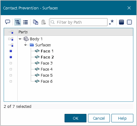
If you only have a few part surfaces in the model and they are easily identifiable, using the object selection dialog to select the part surfaces is the easiest and simplest method.
However, if you have many part surfaces or prefer to select part surfaces interactively in the Graphics window, use the Select Part Surfaces Interactively dialog.
- To access the Select Part Surfaces Interactively dialog, first ensure that there is a scene open, as the dialog requires selection of part surfaces in the Graphics window.
-
Then, right-click the
Contact Prevention node and select
Select Part Surfaces...
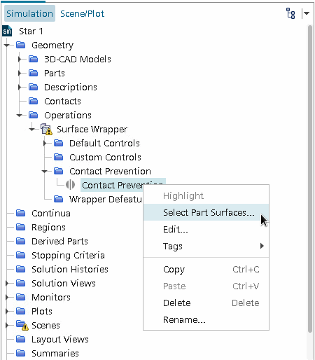
The Select Part Surfaces Interactively in-place dialog opens: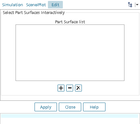
- Select the part surfaces for the contact prevention set using the mouse in the Graphics window (press <Ctrl> for multiple selections).
-
Once you have made the appropriate selections, click
 to add the part surfaces to the list. Alternatively, right-click a selected part surface and select
Add Part Surface.
Selected part surfaces appear blue in the display, indicating they belong to a set.
 -
If part surfaces must be removed, select the part surfaces in the list box or in the display and click
 to remove them. Alternatively, right-clicking on a part surface in the display provides a
Remove Part Surface option. Clicking
 removes all part surfaces from the list box.
Select at least two part surfaces in order for the contact prevention to be valid.
 - Once the selections are complete, click Apply to apply the changes, and then Close to return to the simulation tree.
Two Group Contact Prevention
-
Selecting
Two Group Contact Prevention Set creates a node that is called
Contact Prevention 1.
The properties of this node are shown below:
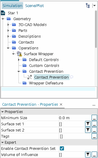
-
Part surfaces for each group are selected in the same way as for a single contact prevention set.
If part surfaces are selected interactively, a list box for both the first and second group is provided:
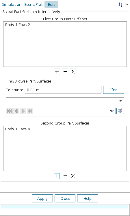
- Part surfaces can be added or removed from groups in the same way as for a single contact prevention set, but care should be taken that they are added to the correct group.
- You can also use the Find/Browse Part Surface finder to identify part surfaces within a specified tolerance of the surfaces in the first group, and add them to the second group.
- To use the Find/Browse Part Surface finder, first add one or more part surfaces to the first group.
-
Then enter the
Tolerance, which specifies the search distance from the surfaces in the first group, and click
Find.
The tool finds all surfaces that have any part of their surface within the tolerance, and adds them to the drop-down menu.
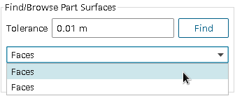
Browse buttons
 are
available to inspect individually each part surface the tool finds.
-
To add a part surface to the second group, select the part surface from the drop-down menu and click
 . To add all part surfaces in the menu, click
 .
Surfaces that are selected for the first group appear blue in the display, while surfaces in the second group appear orange.
 - Select at least one surface for both the first and second group in order for the contact prevention to be valid.
Minimum Size
As a guideline, set this value to be approximately the largest distance between the surfaces that you want to keep separated.
Although contact prevention occurs if the distance between the surfaces is less than the search distances, it is not guaranteed to work in this case.
Enable Contact Prevention Set
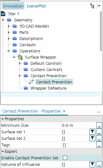
By default, the Enable Contact Prevention Set option is on.
Using Volume of Influence to Limit Contact Prevention
- Click the ellipsis (...) to the right of the property to launch the Volume of Influence selection dialog.
-
Choose one or more parts that define the volume within which contact prevention is to apply and click
OK.
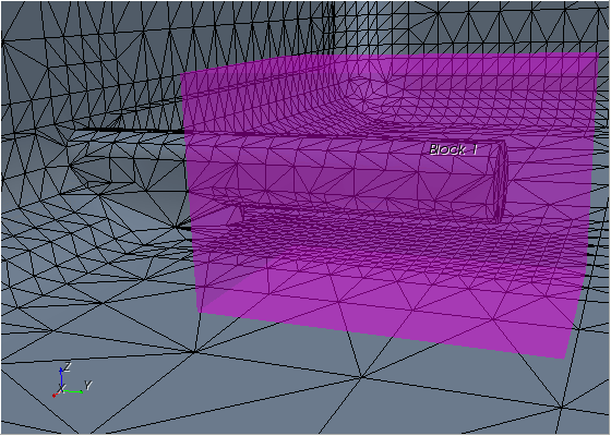
As an example, the dialog below selects Block 1 to define the volume of influence.
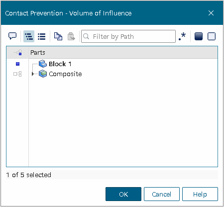
When the surface wrapper runs, contact prevention is only applied to the area of participating surfaces that lie within the specified volume. The wrapper does not prevent contact for the remainder of these surfaces outside the specified volume. For this example, the volume of influence is applied to the contact prevention set created for the sensor boundary in the manifold surface wrapping tutorial. The resulting surface wrap is modified as shown below. The outline of the volume shape Block 1 is also shown.