Creating an Injector
Create the local Cartesian coordinate system.
-
Right-click the
node and select
.
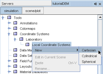
-
Using the in-place dialog, define the coordinate system with the following settings:
Property Setting Origin X: -0.5 m Y: 0.16 m Z: 0.0 m i Direction X: 1 Y: 0 Z: 0 j Direction X: 0 Y: 1 Z: 0 The dialog appears as follows.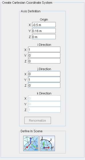
- Click Create then Close.
To create the presentation grid using the Properties window:
-
Right-click the manager and select .
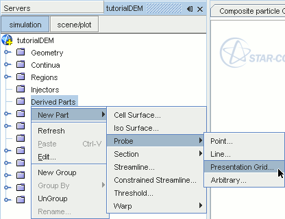
- Using the in-place dialog, click Create and Close.
An arbitrary plane is created with the default settings.
To modify the settings:
- Rename the node to Injector Grid.
-
Use the following settings to define the injector grid:
Property Setting X Resolution 10 Y Resolution 10 Coordinate System Laboratory->Cartesian 1 Point 1 [0.2, -0.05, 0.0] m,m,m Point 2 [0.0, -0.05, 0.2] m,m,m Origin [0.0, -0.05, 0.0] m,m,m Parts [Region, Region: GrainSystem] 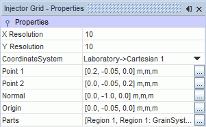
Finally, the particle injector is created.
- Right-click the node and select .
- Select the node and set the Type to .
-
To assign the injector to the previously created injector grid, click the ellipsis next to the
Inputs property.
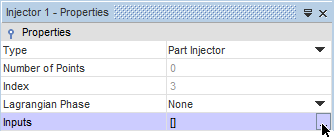
-
In the
Inputs selection dialog, expand the
node and tick the checkbox next to the
node.
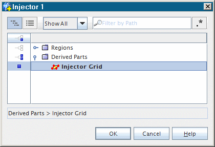
- Click OK to close the dialog.
-
While still at the
node, set the
Lagrangian Phase to
.
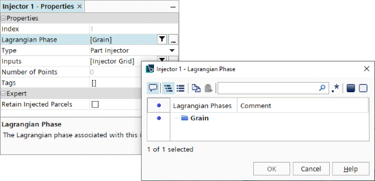
-
Expand the
Injector 1 node and set the following properties:
Node Property Setting Conditions  Flow Rate Distribution
Method Per Injector Point  Flow Rate Specification
Method Particle Flow Rate Values 
Value 0.01 m 
Value $Time < 0.5 ? 100 : 0 
Value [0.0, -2.0, 0.0] m/s - Save the simulation.