Setting Up a Visualization Scene
Create a scalar scene to provide a visual representation of the grain particles within the fluid system.
- Right-click the node, and select .
- Click the Scene/Plot button above the object tree.
-
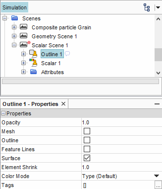
Select the
node.
- Deactivate the Outline property.
- Activate the Surface property.
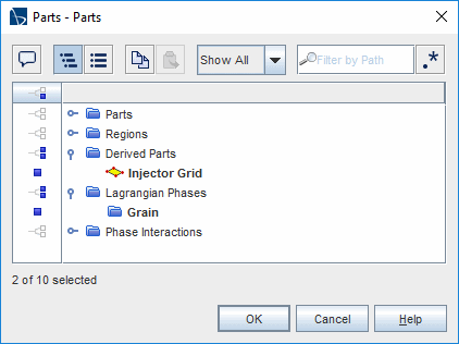
- Right-click the manager and select .
-
In the Parts dialog, select and . Click OK.
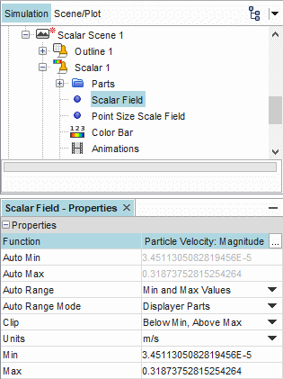
-
Select the node and set the Function to .
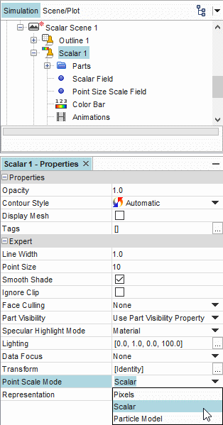
-
Select the node and set the Point Scale Mode to .
- Select the node and activate the Enabled property.
-
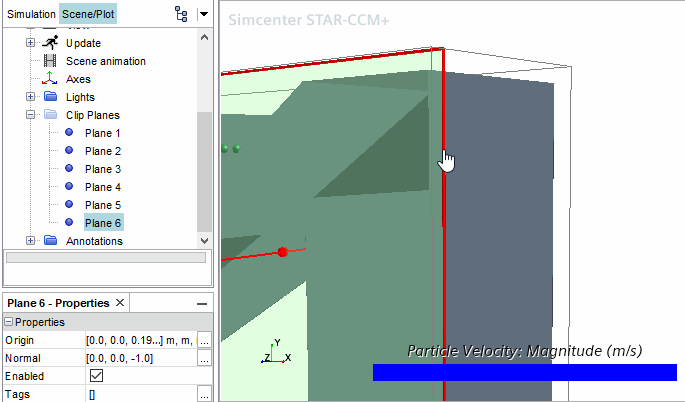
In the scene display, position the cursor within the red bounds of the clip
plane, and then click and drag the plane tool in the z-direction. Move the plane
until it gets close to the edge of the conveyor, or where the z-coordinate of
the Origin property is about
0.19.
-
Rearrange the color bar and display to provide the following view.

To export an image of
the visualization at every time-step:
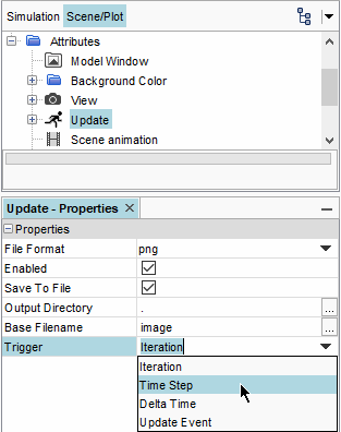
- Select the node and set the Trigger to .
-
Activate the checkbox for the Save to File
property.
-
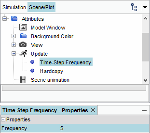
Expand the manager, select the node, and set the Frequency to
5.
- Save the simulation.