Generating the Mesh
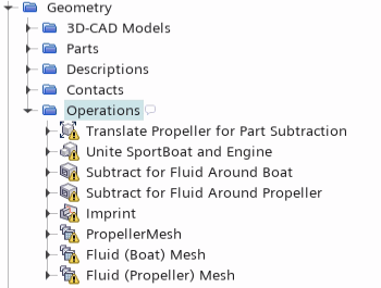
The starting simulation contains predefined mesh operations that are fully set up and ready for execution. These operations prepare the geometry parts, subtract the fluid volume parts, and generate appropriate meshes for the fluid and solid regions.
-
Expand the
node.

The operations pipeline does the following:- arranges the geometry parts for part subtraction using translation and unite operations
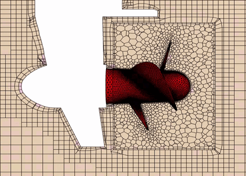
- generates a tetrahedral mesh for the propeller blades and propeller hub
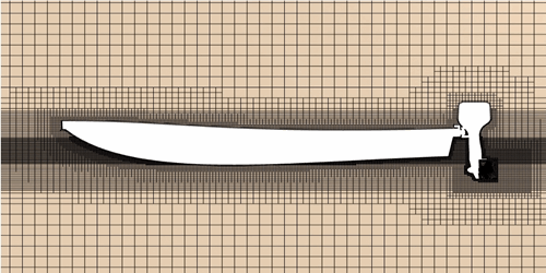
- generates a trimmed mesh for the fluid around the boat
- generates a polyhedral mesh for the fluid around the propeller
In the starting simulation, the Mid-Side Vertex Option for the solid propeller region is set to Add - Linear Interpolation. With this setting, Simcenter STAR-CCM+ adds mid-side vertices to the mesh when you run the simulation.
- Right-click the Operations node and select Execute All.
- When the mesh generation is complete, open the .
In the mesh scene, you define two displayers—one for the fluid mesh, and one for the propeller mesh. For the fluid, you visualize the mesh on a plane section through the fluid regions:
- Right-click the Derived Parts node and select
-
In the
Create Plane Section dialog, set the following properties:
Property Setting Input Parts and Fluid (Propeller) (deselect the Propeller region) Origin [-0.48063, 0.3, -0.38072] m,m,m Normal [0.0, 1.0, 0.0] m,m,m Displayer No Displayer - Click Create then Close.
- Expand the Scenes node.
- Right-click the Mesh Scene 1 node and select .
- Rename the Mesh 1 displayer to Fluid Mesh and the Mesh 2 displayer to Propeller Mesh.
-
Edit the Mesh Scene 1 node and set the properties of
each displayer as follows:
Node Property Setting Fluid Mesh Representation Volume Mesh  Parts
Parts
Parts (deselect any other parts) Propeller Mesh Surface Activated Color Mode Constant  Parts
Parts
Parts  Color
Color
Color Red -
Click (Save-Restore-Select Views) and select
.
You can visualize the fluid mesh around the boat (trimmed), the solid propeller mesh (tetrahedral), and the fluid mesh around the propeller (polyhedral) by zooming in the areas of interest:


- Save the simulation.