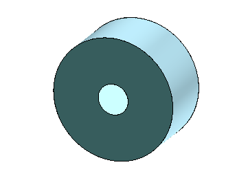
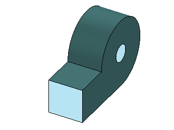
Fans cool electronic devices by drawing cool air over the components' heat sinks. In radial fans, the gas flow is perpendicular to the fan's axis. They generally produce high pressures and low flow rates.
The
Electronics Cooling Toolset supports two types of
 Radial Fan QuickParts:
If none of the built-in radial fans are suitable, you can define a
 Custom radial fan whose geometry is based on a
Construction Geometry that you specify.
A Radial Fan QuickPart physically separates the inflow and outflow surfaces in space—the volume within the fan is not modeled. Fluxes that cross the inflow surface are transformed and applied to the outflow surface. The pressure rise that the Radial Fan QuickPart imposes across the two surfaces of the contacting gas QuickPart depends on the fan performance curve that you specify. A fan performance curve describes the pressure rise across the fan—that is the static pressure measured downstream of the fan minus the total pressure that is measured upstream of the fan—as a function of the volumetric flow rate.
An optional heat source allows you to model the heat that is generated in operation of the fan.
| Note | Radial Fan QuickParts are currently not supported for liquid domains.
|
Radial Fan—Properties
The following properties are common to all types of radial fans:
| Name
|
Specifies the name of the heat sink under which it is stored in the tree.
|
| Geometry
|
- Local Origin
- Specifies the position of the radial fan's local coordinate system. See X_or, Y_or, Z_or in the
Graphics window. It is used for placing the fan in the simulation domain. The following options are available:
-
- A: Center of the Zmin face.
- B: Center of the fan geometry.
- C: Center of the Zmax face.
- Custom: This value appears when you set the local origin interactively within the
Graphics window, see
Placing Object Interactively.
|
| Placement
|
See
Placement properties.
|
| Physics
|
- Blower Heat Generation Rate
- Specifies the total heat generated by the fan.
- Fan Curve Type
- Controls the specification of the fan performance curve. The following options are available:
-
- Linear:
Defines the fan curve as a linear function. The pressure rise across the Fan Surface is calculated as
where and are the specified
Maximum Pressure and
Maximum Flow, respectively.
- Table:
Defines the fan curve as a table of pressure rise versus volumetric flow rate as indicated by the imported
Fan Curve File (*.csv). After the import, select the appropriate
Pressure Units and
Volume Flow Units. The pressure rise is calculated by linear interpolation between the data points in the table. Outside the intervals, the nearest limit is used.
- A fan performance curve provides the pressure rise across the fan for a specific fluid temperature and fan rotation rate.
- If your data correspond to some standard temperature, you must manually modify the fan performance curve to suit the temperature in your simulation using established fan laws:
- If your data correspond to some standard fan rotation rate, the
Electronics Cooling Toolset automatically adjusts the fan performance curve to suit the fan rotation rate in your simulation:
- where:
-
- is the specified
Data Rotation Rate, that is the fan rotation rate at which the fan performance curve was measured.
- is the specified
Operating Rotation Rate, that is the fan rotation rate in your simulation.
- and are the measured pressure rise and the pressure rise in your simulation, respectively.
- and are the measured volumetric flow rate and the volumetric flow rate in your simulation, respectively.
|
The following properties characterize the different types of radial fans:
Templated—Specific Properties
| Geometry
|
- Fan Radius
- Specifies the radius of the fan volume.
- Inlet Radius
- Specifies the radius of the inflow surface.
- Width
- Specifies the extent of the fan volume in z-direction, in the radial fan's local coordinate system. See X_or, Y_or, Z_or in the
Graphics window.
- Inlet Type
- Specifies the location of the inflow surface. The following options are available:
-
- Front: Zmax side of the fan.
- Back: Zmin side of the fan.
- Dual: Each side of the fan (Zmin and Zmax).
|
TemplatedWithVolute—Specific Properties
| Geometry
|
- Fan Radius,
Inlet Radius,
Width,
Inlet Type
- As for Templated radial fan.
- Volute Length
- Specifies the length of the volute.
- Outlet Width
- Specifies the width of the outflow surface.
|
Custom—Specific Properties
| Geometry
|
- Selected Construction Geometry
- Specifies the
Construction Geometry that describes the fan volume.
- Select Inlet Faces,
Select Outlet faces
- Specify the inflow surfaces and the outflow surfaces of the Selected Construction Geometry to determine the flow direction through the fan.
|
 Radial Fan QuickParts:


 Custom radial fan whose geometry is based on a
Construction Geometry that you specify.