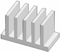
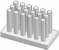
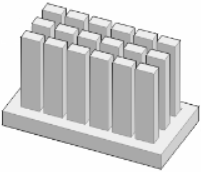
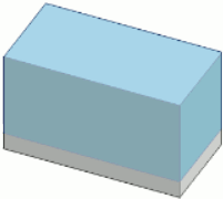
Heat sinks cool electronic components by transferring the generated heat into the surrounding fluid.
The
Electronics Cooling Toolset supports the following
 Heatsink QuickParts:
While Plate Fin, Pin Fin, and Cross Cut heat sinks resolve the geometry of a real heat sink using simple shape templates, a Compact heat sink enables you to model the behaviour of a heat sink without considering geometric details. The Compact heat sink uses a
Porous Medium approach for the fin region to capture the effects on the overall fluid flow and heat transfer. With this approach, you do not have to define a fine mesh around the fins or pins of a heat sink.
If none of the built-in heat sinks are suitable, you can define a
 Custom heat sink whose geometry is based on
Construction Geometries that you specify.
Heat Sink—Common Properties
The following properties are common to all types of heat sinks:
| Name
|
Specifies the name of the heat sink under which it is stored in the tree.
|
| Geometry
|
- Local Origin
- Specifies the position of the heat sink's local coordinate system. See X_or, Y_or, Z_or in the
Graphics window. It is used for placing the heat sink in the simulation domain. The following options are available:
-
- A: Center of the bottom (Zmin) face.
- B: Xmin/Ymin corner of the bottom (Zmin) face.
- C: Xmin/Ymax corner of the bottom (Zmin) face.
- Custom: This value appears when you set the local origin interactively within the
Graphics window, see
Placing Object Interactively.
|
| Placement
|
See
Placement properties.
|
The following geometry and physics properties characterize the different types of heat sinks—if you specify geometry parameters that lead to an invalid body, the parameters that require correction are highlighted in red:
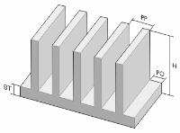
Plate Fin—Specific Properties
|
Geometry
|
|
- X,
Y
- Specify the dimensions in x- and y-direction, in the heat sink's local coordinate system. See X_or, Y_or, Z_or in the
Graphics window.
- Height - (H)
- Specifies the height from base to top of the fins.
- Base Thickness - (BT)
- Specifies the thickness of the heat sink's base.
- Fin Offset - (PO)
- Specifies the offset of the plate fins from the base's sides.
- Fin Thickness
- Specifies the thickness of each plate fin.
- Number of Fins
- Specifies the number of plate fins that are placed on the heat sink's base.
|
| Physics
|
- Fins Bonded to Base
- Controls if the fins of the heat sink are bonded to or extruded from the base.
- When
Off, a
Material property is available to specify the overall material of the extruded heat sink.
- When
On, a
Base Material, and a
Fin Material property specify the material of the heat sink's base and fin respectively. A
Contact Resistance property sets the contact resistance between the fins and the heat sink's base.
- You can choose the materials from the Solid Sim Materials that you define in the
Setup panel.
|
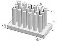
Pin Fin—Specific Properties
|
Geometry
|
|
- X,
Y
- Specifies the dimensions in x- and y-direction, in the heat sink's local coordinate system. See X_or, Y_or, Z_or in the
Graphics window.
- Height - (H)
- Specifies the height from base to top of the fins.
- Base Thickness - (BT)
- Specifies the thickness of the heat sink's base.
- Min Pin Offset - (PO)
- Specifies the minimum offset of the pin fins from the base's sides.
- Pin Radius
- Specifies the radius of each pin fin.
- Pin Pin Spacing
- Controls the spacing between the pin fins. The following options are available:
-
- Pin-Pin Distance: Sets the spacing based on the distance between the pin fins within one line. This option activates the
Pitch - (PP) property that specifies the distance from one pin fin to the next.
- Number of Pins: Sets the spacing based on the number of pin fins within one line. This option activates the
Count X and
Count Y properties that specify the number of pin fins in x- and y-direction, respectively, in the heat sink's local coordinate system.
- Rows Staggered
- Controls if the pin fins are arranged in-line or staggered.
|
| Physics
|
- Material
- Defines the material of the heat sink. You can choose the material from the Solid Sim Materials that you define in the
Setup panel.
|
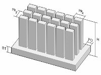
Cross Cut—Specific Properties
|
Geometry
|
|
- X,
Y
- Specifies the dimensions in x- and y-direction, in the heat sink's local coordinate system. See X_or, Y_or, Z_or in the
Graphics window.
- Height - (H)
- Specifies the height from base to top of the fins.
- Base Thickness - (BT)
- Specifies the thickness of the heat sink's base.
- Min Pin Offset - (PO)
- Specifies the minimum offset of the pin fins from the base's sides.
- Pin Length
- Specifies the length of each pin fin.
- Pin Width
- Specifies the width of each pin fin.
- Pin Pin Spacing
- Controls the spacing between the pin fins. The following options are available:
-
- Pin-Pin Distance: Sets the spacing based on the distance between the pin fins within one line. This option activates the
Pitch - (PP) property that specifies the distance from one pin fin to the next.
- Number of Pins: Sets the spacing based on the number of pin fins within one line. This option activates the
Count X and
Count Y properties that specify the number of pin fins in x- and y-direction, respectively, in the heat sink's local coordinate system.
- Rows Staggered
- Controls if the pin fins are arranged in-line or staggered.
|
| Physics
|
- Material
- Defines the material of the heat sink. You can choose the material from the Solid Sim Materials that you define in the
Setup panel.
|
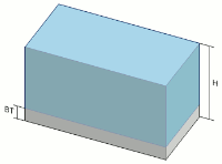
Compact—Specific Properties
|
Geometry
|
|
- X,
Y
- Specifies the dimensions in x- and y-direction, in the heat sink's local coordinate system. See X_or, Y_or, Z_or in the visualization display.
- Height - (H)
- Specifies the height from base to top of the porous block.
- Optional Base
- Controls if the heat sink has a base or not. When
Present, a
Base Thickness - (BT) property specifies the thickness of the base. For the physics, you specify a
Base Material and a
Contact Resistance property.
|
| Physics
|
- Base Material
- Specifies the material of the heat sink's base. You can choose from the Solid Sim Materials that you define in the
Setup panel.
- Fin Properties
- Specifies the properties of a porous medium that is used to mimic the effect of actual fins on the overall flow and heat transfer.
- Each parameter requires an
XXComponent, a
YY Component, and a
ZZ Component that represent
the diagonal components of a Principal Tensor. The
following parameters are available:
-
- Porous Inertial Resistance
- Specifies the inertial resistance caused by the modeled fins, see
Porous Media Drag Model Region Settings.
- Porous Viscous Resistance
- Specifies the viscous resistance caused by the modeled fins, see
Porous Media Drag Model Region Settings.
- Solid Thermal Conductivity
- Specifies the thermal conductivity of the modeled fins' material, see
Solid Thermal Conductivity.
- Porosity
- Specifies the ratio of open volume to total volume within the heat sink.
- Contact Resistance
- Specifies the contact resistance between the fins and the heat sink's base.
|
Custom—Specific Properties
| Geometry
|
- Base
- Specifies the Construction Geometries that define the geometry of the heat sink's base.
- Fins
- Specifies the Construction Geometries that define the geometry of the fins.
|
| Physics
|
- Fins Bonded to Base
- Controls if the fins of the heat sink are bonded to or extruded from the base.
- When
Off, a
Material property is available to specify the overall material of the extruded heat sink.
- When
On, a
Base Material, and a
Fin Material property specify the material of the heat sink's base and fin respectively. A
Contact Resistance property sets the contact resistance between the fins and the heat sink's base.
- You can choose the materials from the Solid Sim Materials that you define in the
Setup panel.
|
 Heatsink QuickParts:
 Custom heat sink whose geometry is based on
Construction Geometries that you specify.
