Resistance
A Resistance describes any electronic component that permits the passage of gas and generates heat.
 Resistance QuickPart does not resolve the internal structure of the component but uses a
Porous Medium approach to describe the effect of the component on the overall flow and heat transfer. With this approach, you can model complex power supplies without considering geometric details. It is particularly useful for modeling PCB racks.
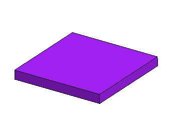
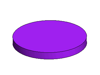
The Electronics Cooling Toolset supports the following simple shape templates:
If none of the built-in shape templates are suitable, you can define a
 Custom resistance whose geometry is based on a
Construction Geometry that you specify.
| Note | The fluid that is contained in a Resistance QuickPart is the Default Gas material that you specify in the Setup panel. Resistance QuickParts are currently not supported in liquid domains. |
Resistance—Properties
The following properties are common to all resistance types:
| Name | Specifies the name of the resistance under which it is stored in the tree. | |
| Geometry |
|
|
| Placement | See Placement properties. | |
| Physics | Specifies
the properties of a porous medium that is used to mimic the
effect of the actual component on the overall flow and heat
transfer. The Porous Inertial Resistance, the Porous Viscous Resistance, and the Solid Thermal Conductivity require the input of an XX Component, a YY Component, and a ZZ Component that represent the diagonal components of a Principal Tensor in the local coordinate system of the resistance. See X_or, Y_or, Z_or in the Graphics window.
|
|
The following properties characterize the various resistance types:
Block—Specific Properties
| Geometry |
|
|
Cylinder—Specific Properties
| Geometry |
|
|
Custom—Specific Properties
| Geometry |
|
|

