Dynamic Sectioning View
Dynamic Sectioning View allows you to visualise the internals of a geometry using the clipping planes method. You can create and visualise up to three planes at a given time to display a smaller portion of the geometry.
The following screenshot shows how the
dynamic sectioning view appears in the graphic window for the YZ plane:
-
To use dynamic sectioning, do one of the following:
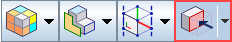
- In the toolbar at the top of the 3D-CAD view scene, click
 Display Cut Parts using Multiple Planes.
 - In the graphics window, select a planar or revolved face, then right-click and select Create Section. You can also apply dynamic sectioning to reference planes.
The Dynamic Sectioning panel appears on the left of the graphics window.
- In the toolbar at the top of the 3D-CAD view scene, click
- In order to view the internals of the geometry, activate Turn On Clipping.
-
In the Dynamic Sectioning panel for a chosen section, you
can select from four types of plane:
- ZX Plane
- plane normal is the Y axis.

- XY
Plane - plane normal is the Z axis.

- YZ
Plane - plane normal is the X axis.

- Reference
Plane - allows you to select a planar surface to act as the
clipping plane.

- ZX Plane
- plane normal is the Y axis.
-
Once you select your preferred plane, you have two options to control the plane:
- You can move the plane at various positions or angles by clicking and dragging the plane widget in the Graphics Window.
- Alternatively, you can use the Offset option in the sectioning panel to manually define the distance between the cutting plane and the origin.
-
To reverse the side of the geometry that is clipped by the plane, activate the
Reverse Plane Normal option:

-
In order to visualise inside solid bodies, deactivate
Show Cap.
The clipping plane appears without the cap color.
-
To adjust the
Cap Color Option, you can choose from the following options:
- Specified Color - allows you to choose your preferred cap color.
- Body Color - cap color is the same as the body color.
- Click Close in the Dynamic Sectioning panel.
-
To reactivate the dynamic sectioning scene, select the
Toggle Section View icon in the toolbar.
To expose more of the model than one plane permits, you can activate up to three clipping planes simultaneously.
As an example, suppose that you are working on a truck chassis and want to view the chassis profile along two sections. You can set properties as follows:
- Section 1 - select XY Plane and Red for Cap Color.
- Section 2 - select ZX Plane and Blue for Cap Color.