3D-CAD Models
A 3D-CAD model is a geometry body that is created in Simcenter STAR-CCM+ using the feature-based parametric solid modeler, 3D-CAD. 3D-CAD models can include geometry that you import from elsewhere, for example, an NX part or assembly.
Creating a 3D-CAD Model
To create a 3D-CAD model:
- Right-click on the node and select .
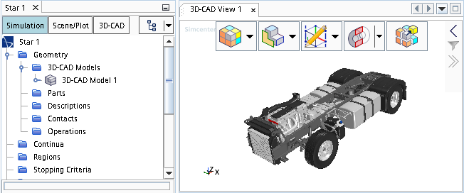
This action creates a 3D-CAD model node under the node and activates 3D-CAD. When 3D-CAD is open, the 3D-CAD model tree is shown in the explorer pane and a 3D-CAD View scene is displayed in the Graphics window. You can begin adding features to the model by creating a sketch or sketch plane, or by importing geometry from an external CAD file.
3D-CAD Model Properties
| Distinguish Bodies Color Palette | Allows you to choose a pre-defined color palette when visualizing bodies and named faces in the 3D-CAD View scene. For more details on the color palette, see Using a Color Palette. | |
| Part Update Method | Update | When you modify the 3D-CAD model, either directly within
3D-CAD, or through a design parameter, you must manually update
the model. You must also manually update the geometry parts that
are created from the 3D-CAD model. For example, if you make changes to the 3D-CAD model that result in additional bodies, you must manually create the corresponding geometry parts from the 3D-CAD model, in addition to the existing geometry parts. If the changes to the 3D-CAD model result in the removal of bodies, you must manually delete the corresponding obsolete geometry parts. |
| Synchronize | Synchronizing the geometry parts with the 3D-CAD model
automatically updates the changes that you make in the 3D-CAD
model. For example, if the changes to the 3D-CAD model result in additional parts, the corresponding geometry parts are created. If the changes to the 3D-CAD model result in the removal of parts, the corresponding geometry parts are removed. When synchronized, named entities in the 3D-CAD model (faces/edges/vertices) are linked to the equivalent geometry part objects (surfaces/curves/points) and are also updated to match the changes made in the 3D-CAD model.For more information, see Synchronizing Geometry Parts with the 3D-CAD Model. |
|
Editing an Existing 3D-CAD Model
You can edit existing 3D-CAD models and resume from where you left off. To edit a 3D-CAD model:
- Right-clicking on the model node under the manager node and select
3D-CAD launches and opens the 3D-CAD View scene. You can resume working on your 3D-CAD model. When you have finished editing the model, you can close 3D-CAD and return to the simulation tree. If you already used the model to create geometry parts, update these parts for the changes to take effect.
| Note | Further steps are required if you used the geometry to generate a mesh or run a simulation. See Modifying a 3D-CAD Model. |
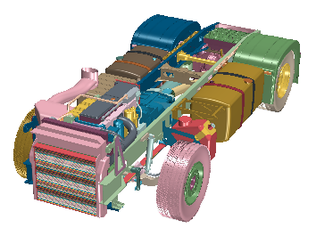
Visualizing a 3D-CAD Model
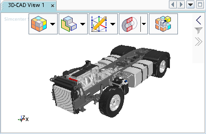
In this scene, you can rotate and zoom in to view the geometry model, as well as hide and show select faces and bodies. To display all hidden geometry and restore the view, right-click a blank space and select Restore All followed by the appropriate item that you want to restore. You can use the Visibility toolbar to control how geometry is displayed as well as what is displayed.
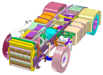
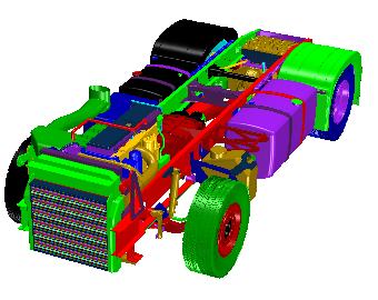
Using Color Palette
 (default palette) |
 |
|
 |
 |
|
 |
 |
|
- Click the Close 3D-CAD button to exit 3D-CAD.
- Right-click the node and select New.
- In the Properties window, click the custom editor for Swatches and choose the colors that you want to add to the color palette.
Exiting 3D-CAD
To exit 3D-CAD and return to the main simulation tree:
- Click the Close 3D-CAD button.
The 3D-CAD View scene automatically closes, and view settings in the scene are discarded. You can save these settings before exiting 3D-CAD by storing the current view.