Setting the FSI Coupling
You define two-way coupled FSI between the solid diaphragm and the fluid overset region.
To apply motion models and activate coupling:
- Right-click the node and select .
- Repeat the previous step and select .
- Select the node and set Motion to Morphing.
- Select the node, and set Specification to Floating.
-
Select the node, and set Motion to
Solid Displacement.
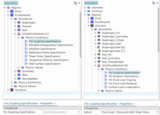
These steps complete the set up for the coupling in the direction structure to fluid. You can verify the coupling by looking at the FSI Coupling Specification on the FSI interface boundary in the fluid overset region. The fluid overset region FSI Coupling Specification is set to Solid Displacement as shown in the image below.From the fluid to the structure, the coupling is set by default to be the fluid traction. You can verify this coupling by looking at the FSI Coupling Specification on the FSI interface boundary in the solid region. As shown in the image below, the solid region FSI Coupling Specification is set to Fluid Load - Pressure & Wall Shear Stress.

You define the motion of the plunger using a
Translation motion. You can define the translational
velocity as the derivative of the position of the plunger with respect to time. This
simulation contains a predefined expression report that defines the plunger position
as:
${Time} <= <4.0 s> ? <-2.2 mm> * ${Time} / <4.0s> : <-2.2 mm>
This expression reads that if the solution time is less than 4.0 seconds then the position output is -2.2 mm divided by 4.0 seconds, multiplied by the current solution time. If the solution time is greater than 4.0 seconds then the position output is -2.2 mm. The output of the PlungerPosition is the displacement of the Plunger in the following time-step.
-
To create a report that defines the velocity of the Plunger as the time
derivative of the PlungerPosition report:
-
To define the translation motion:
- Save the simulation.