Generating the Mesh
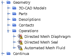
The starting simulation contains predefined mesh operations. These operations generate appropriate meshes for the fluid and solid region.
-
Expand the node.

The existing operation set performs the following tasks:- Generates a directed mesh for the diaphragm.
- Generates a directed mesh for the seal.
- Generates a polyhedral mesh with prism layers for the fluid background and fluid overset parts with mesh refinements around the area influenced by the deformation of the diaphragm.
- Right-click the node and select .
- In the Create Automated Mesh Operation dialog, select the Plunger part and select the Surface Remesher model.
- Rename Automated Mesh to Automated Mesh Plunger.
- Select the node and set Base Size to 5mm.
- Right-click the Operations node and select Execute All.
- When the mesh generation is complete, create a mesh scene.
For visualization, you can add mesh displayers that show the
different regions, and surface displayers for the plunger and housing
geometry.
- Rename node to Fluid.
- Right-click the node and select .
- Repeat step 9.
- Rename to Fluid Overset and Mesh 2 to Structure.
-
Edit the Mesh Scene 1 node and set the following
properties:
Node Property Setting Fluid Surface Deactivated  Parts
PartsParts Fluid Overset  Mesh
Color
Mesh
ColorMesh Color Violet Dark  Parts
Parts
Parts Structure  Mesh
Color
Mesh Color Orange  Parts
PartsParts (all boundaries) -
To orient the view, activate and press s.
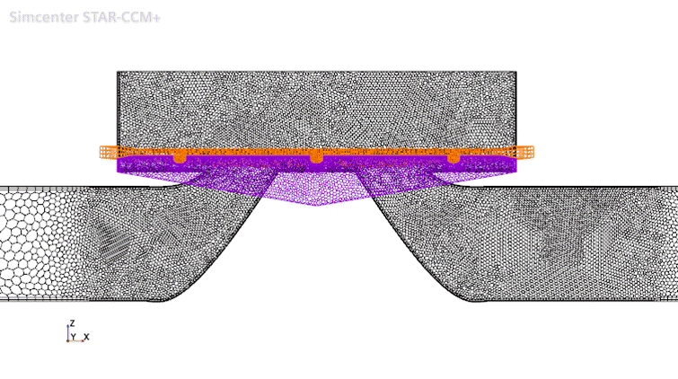
The mesh and other geometry parts look as follows:

The black mesh is the fluid region and the background mesh required by the fluid overset region, the purple mesh is the fluid overset region, and the orange mesh is the solid region.
- Save the simulation.