Setting Up Shell Region and Boundary Conditions
Create a shell region and define the boundary conditions.
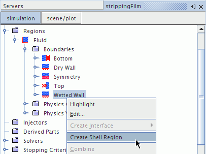
In this tutorial, the binary liquid film forms on the Wetted Wall boundary of the Fluid region. A shell region is required for all boundaries on which the fluid film is to flow. You create this shell region from the Wetted Wall boundary.
To create a shell region and define the boundary conditions:
-
Right-click the
node and select
Create Shell Region.

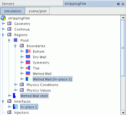
A new shell region is added to the simulation tree. In addition, an interface is formed between the fluid region and the shell region, based on the geometry of the Wetted Wall boundary surface.

Assign the fluid film phase to the Wetted Wall Shell region:
-
Select the
node and set the
Continuum to
Fluid Film.

Specify the actual fluid film boundary conditions using the nodes within the Wetted Wall Shell region. These boundaries are formed from the edges of the original Wetted Wall boundary from which the shell region was created. By default all boundaries are set to no-slip wall, except the Interface to Fluid [In-place 1], which is set to the Fluid-Film Boundary type.
Change the boundary type of the Bottom edges, Symmetry edges, and Top edges boundaries to their appropriate types.
-
Edit the
node and set the boundary types as follows:
Boundary
Type
Bottom edges
Outlet
Symmetry edges
Symmetry Plane
Top edges
Mass Flow Inlet
The Wetted Wall is heated in one section only. You can define the heat flux in a field function.
- Right-click the node and select from the pop-up menu.
- Rename the User Field Function 1 to Heat Flux Wetted Wall.
-
Select the
Heat Flux Wetted Wall node and set the following properties:
Property Setting Function Name heatFluxWettedWall Definition ($$Position[2] <= 0.2)? 0 : 3000 -
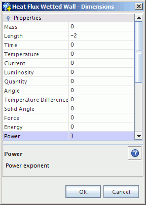
Set
Dimensions as
Length =
-2 and
Power =
1.

Specify the Wetted Wall heat flux.
-
Edit the
node and set the following properties:
Node Property Setting Condition Heat Flux Method Field Function Scalar Function Heat Flux Wetted Wall
Set the boundary conditions for the inlet of the fluid film shell.
-
Edit the
node and set the following properties:
Node Property Setting Fluid Film Thickness Value 0.001 m Mass Flow Rate Value 0.015 kg/s Species Mass Fraction Value [0.5, 0.5] Total Temperature Value 293.15 K - Save the simulation.