View Prism Layer Cells Using a Cell Set
Simcenter STAR-CCM+ provides a field function that allows you to view cells that are generated by the Prism Layer Mesher. You can use the same function to view prism layers that the Advancing Layer Mesher model creates.
Use this function in combination with a cell set to define the selection of prism layer cells that you want to view in a displayer.
You can view prism layer cells as a cell set in cases which use the prism layer meshing model combined with the following volume meshers:
- Polyhedral Mesher
- Generalized Cylinder Mesher (also with Polyhedral Mesher)
- Tetrahedral Mesher
- Trimmed Cell Mesher
- Thin Mesher
- Extruder Mesher
- Directed Mesher
Before Creating the Cell Set:
- The mesh that you use for this feature must be created in Simcenter STAR-CCM+ v8.06 or later. If necessary, regenerate the mesh in Simcenter STAR-CCM+ v8.06 or later.
- This feature does not support imported volume meshes. If necessary, regenerate any imported volume meshes using Simcenter STAR-CCM+ v8.06 or later.
- Ensure that your geometry parts are assigned to regions and that they are meshed using the Prism Layer Mesher model.
To create the cell set:
- Right-click .
-
Select
.
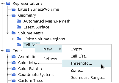
-
In the
Threshold dialog that appears, set:
- Scalar to Prism Layer Cells.
- Extraction Mode to All Above.
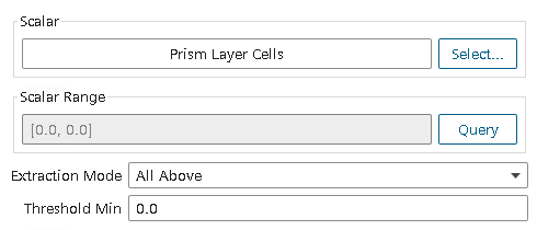
The Threshold value is set to zero by default. However, when Scalar is set to Prism Layer Cells, there is no need to specify the Threshold value as it is automatically set to display all prism layer cells.
-
Set Display to New Surface
Displayer, then click OK.
Selecting New Surface Displayer while a mesh scene is active automatically creates a cell set surface displayer in the mesh scene.
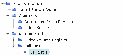
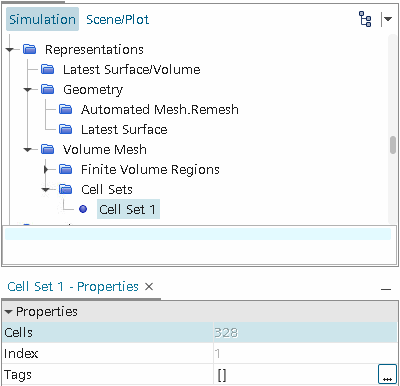
A Cell Set 1 node appears under the Cell Sets manager.
-
To determine the number of cells in the cell set, select the
node.
The number of cells in the cell set is displayed in the Properties window, to the right of the Cells property.
To view the cell set:
- Select the node and click the scene/plot tab.
- Expand thenode and multi-select all nodes except the node.
- Right-click the selected nodes and select .
-
Return to the Simulation tab.
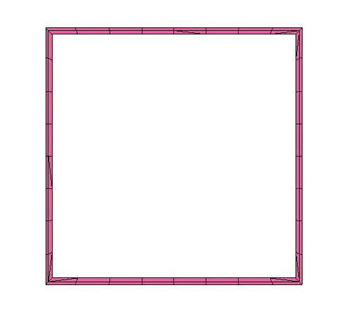
The prism layer mesh cell set is displayed in the Graphics window.
To view a plane section of the cell set:
- Create a plane section.
-
Create a threshold part, using the following settings:
- Set Input Parts to plane section
- Set Scalar to Prism Layer Cells
- Set Extraction Mode to All Above
- Set Display to New Surface
Displayer
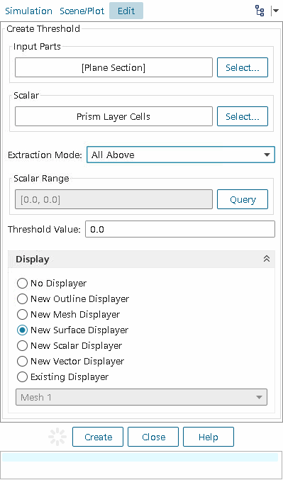
You can use the resulting derived part in a scene displayer to visualize the cross-section of the prism layer.