Visualizing and Analyzing Solution
Overset meshes are automatically created while running a simulation. Two mesh representations are available to visualize the mesh: volume mesh and overset mesh.
By default, the mesh scene is opened using the volume mesh representation. You can change the type in the Properties window of the Mesh node.
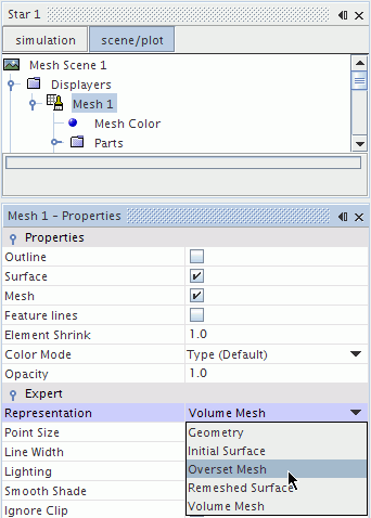
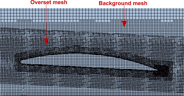
Below is an example of an Overset Mesh representation. This representation shows all background and overset region cells, whether they are active or inactive.
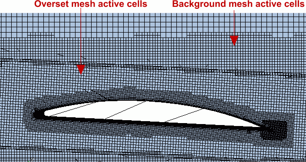
To see only the active cells, select the Volume Mesh representation. Visualization and reporting is done based on this representation.
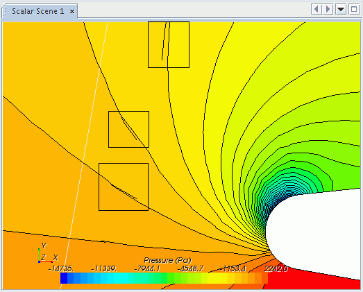
You can visualize the solution on each mesh individually. The nodes of the background mesh most often do not coincide with the nodes of the overset mesh in the overlapping region. If the meshes are not fine enough, this discontinuity can create some visualization issues. One such issue is with contour lines. The discontinuity in the contour lines that are shown below is the result of discretization error and reduces as the mesh is refined.
The overlapping of active cells of the background and the overset region (overlapping zone) also affects the volume integrals. For the volume integrals, the volumes of all active cells are integrated, that is, the overlapping volumes of both the cells in the background and in the overset region are integrated. This way, the volume integrals introduce some inaccuracies for the whole solution domain because of the duplicate integral evaluation of the active cells in the overlapping zone.
This issue does not apply to surface integrals when walls or physical boundaries are either in a background or an overset region. However, when you have boundaries from the background mesh and the overset mesh overlapping each other, this results in overlapping active faces. In this case, you can get inaccuracies for the surface integrals because all active faces are integrated. There is also a duplicate integral evaluation in the overlapping zone of the boundaries.