Troubleshooting Overset Mesh
Several troubleshooting features are available for analyzing the quality of the overset mesh.
You can generate the overset mesh without running the simulation by initializing the Overset Mesh Interface:
- Right-click the Interfaces
node and select Initialize.
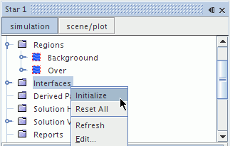
-
If the background and overset regions were not successfully coupled— the overset hole cutting procedure failed, the following error message appears.

- The overset hole cutting usually fails due to the following reasons:
- The overset region has a non-closed overset boundary. It might be necessary to change the overset topology. For more details, refer to Overset Topology.
- There are too few overlapped cells in the overlapping region
built by the overset and background regions. You are advised to ensure at
least 4-5 cells in each mesh to couple the regions. This can either be
achieved by increasing the overset boundary domain or by decreasing the cell
size in the overlapping region as shown in the image below:
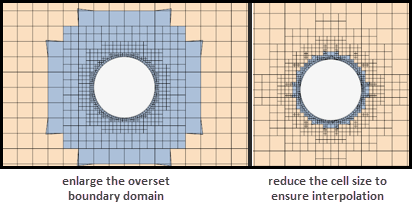
For more details, refer to Generating Overset Meshes.
Checking the Cell Status
To detect mesh insufficiency, you can check the cell status of the overset mesh by creating an Overset Cell Status scalar field. For a list of overset cell status values, see Overset Mesh Field Function Reference.
- Set the scalar mesh representation to Overset Mesh.
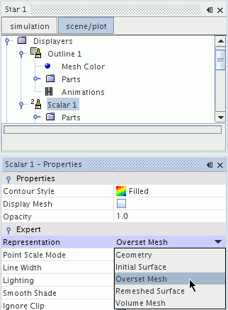
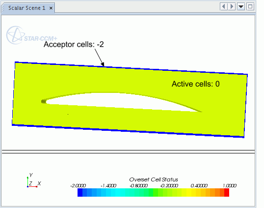
- Check each region separately. It is recommended that you manually
change the scalar bar range from -2.0 to 1.0. In this case, all active cells
have a value of 0, inactive cells have a value of 1, and acceptor cells have a
value of -2. Acceptor cells must separate the active cells from inactive cells;
direct contact between active and inactive cells is not allowed.
Below is the scalar field for the background region. The overset region cells have been deactivated.
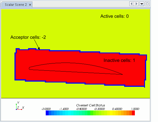
The overset region only includes mesh cells for which the governing equations are solved.
All other scalar field options available for mesh analysis can be found under field function reference.
Reporting the Interpolation Quality for the Overset Interface
To detect the time-step during which low quality interpolation at overset interface occurs, you can create a specific overset report . See Overset Interpolation Quality Report.
Detecting Acceptor Cells with Low Quality Interpolation
To detect the acceptor cells with low quality interpolation, visualize the field function ChimeraGridTestData (see ChimeraGridTestData). The cells with high absolute values are the ones with high interpolation errors. To improve the overset interpolation, improve the cell quality where high interpolation errors occur and check the quality of their donor cells.
Visualizing Acceptor-Donor Dependency
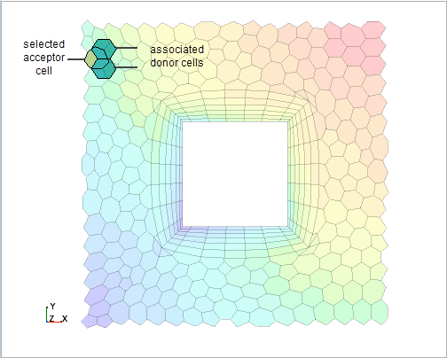
To visualize the associated donor cells of an acceptor cell, you can grow the acceptor cell across an overset interface. This can be done either in the overset region or in the background region.
This visualization helps you understand the data exchange across interfaces and to identify the origin of defective cells.
To visualize the acceptor-donor relation in the following overset example:
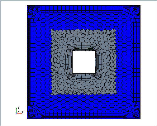
- Plot one region, for example the overset region, with field function
pro-STAR Cell Id:
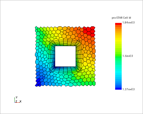
- In the scene, click the acceptor cell of interest and press '.'. This action displays the pro-STAR cell id in the output window.
- Right-click the node and select .
- In the Cell List dialog, specify the Region and enter the
Cell id of the
acceptor cell you selected:
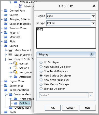
Click OK. A new cell is added to the Cell Sets node.
- To ensure that the acceptor-donor relation is established across the overset interface, right-click the Interfaces node and select Initialize or else click Initialize Solution from the simulation toolbar.
- Right-click the node and select Grow Across
Interfaces.
The associated donor cells are added to the existing cell set.
Viewing Overset Error Cell Sets
When an error occurs during the overset assembly process at the overset interface, a cell set is created that contains all cells with Overset Error Status not equal to 0.
To create successive cell sets in the course of the simulation:
- Select and activate Treat Error as Warning.
Analyzing the Overset Interpolation Type
- Create a scalar scene and display the field function Overset Interpolation Type.
For more information, see Overset Mesh Field Function Reference.