Setting up Prism Layer Shrinkage
If you expect moving bodies in your overset simulation to closely approach another body or wall, you can activate prism layer shrinkage to morph the cells in the small gap that forms. By default, only prism cells at wall boundaries are shrunk. See also: Prism Layer Shrinkage and Prism Layer Shrinkage Reference.
- Design the mesh with at least five prism layers on each wall boundary that forms the gap. You are advised to use the prism layer mesher. The advancing layer mesher can produce topologically non-prismatic elements that are currently not supported. The embedded thin mesher can cause a failed detection of prismatic elements.
In case of shrinkage at sharp edges and corners, set to 0.
- For each overset mesh interface or overset mesh zero gap interface for which you expect a small gap to form, select and activate Prism Layer Shrinkage.
For a zero gap overset interface, you can specify the Minimum Gap Distance to prevent the prism
layers from shrinking when the minimum gap distance is reached. You use this setting
to close of an overset zero gap interface at a specified gap distance.
- Select and set Minimum Gap Distance to a gap width value at which you want the gap to close.
-
By default, the prism layer shrinkage algorithm automatically detects the
number of prism layers that shrink for each boundary. If the Automatic option fails, you can manually
control the prism layer shrinkage in a region follows:
- To switch the adaptive prism layer specification to user-defined, select and set Adaptive Prism Layer Specification to Specified.
- To specify the maximum number of prism layers for shrinkage, select the node and specify the Number of Adaptive Prism Layers.
- To specify the minimum number of active prism layers between boundaries, select the node and specify the Number of Prism Layers in Gap.
- (Optional) The prism layer shrinkage can be triggered directly on Mapped Boundary Interfaces between solid and fluid regions. For fluid-structure-interaction (FSI) simulations, this feature can be especially useful as different discretization methods with different mesh elements are often used and data transfer is achieved using the mapped boundary interface. To activate the Prism Layer Shrinkage Behaviour on such an interface:
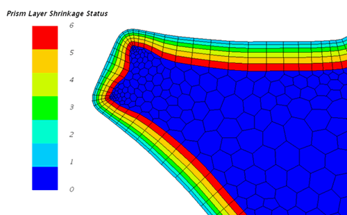
- (Optional) Initialize the solution and check the Prism Layer Shrinkage Status field function.
 All prism cells that are detected successfully are marked with their layer number. See Overset Mesh Field Function Reference
 - (Optional) By default, prism layer shrinkage takes place only at wall boundaries. Other boundary types such as symmetry, velocity inlet, or pressure outlet are ignored. If you require shrinking to occur on other boundary types:
- Select and set Shrinkage Behaviour to Enabled.