Creating a Circuit
Connect the electrical load to the battery module to create a circuit.
A program file containing the electrical load on the battery is provided.
To create a circuit:
- Right-click the node and select Load....
- In the Open dialog, select the Tutorial3CDischargeCylindrical.prg file.
- Click Open.
The program file that you loaded in the previous step represents an electrical load on the battery. To simulate the response of the battery, the electrical load must be connected to the battery in a circuit. Connect the electrical load using the Circuit Solver tool.
- Expand the node.
The Circuit Solver uses Elements and Connections. Each element is either a battery module or a program, and a connection joins elements together in the circuit.
First, you define the battery module and program as elements of the circuit.
-
Right-click the
node and select
Create Circuit Element.
-
Right-click the
node and select
Create Circuit Element.
Next, the positive and negative terminals of the elements are connected.
- Expand the node.
- Multi-select the node and the node.
-
Right-click one of the nodes and select
Create Connection.
-
Repeat for the remaining terminals:
(-) Battery Module and
(+) Tutorial3CDischargeCylindrical.prg.
Each connection is shown under the Circuit Connections node.
To model the effect of ohmic heating, activate the ohmic heating models.
-
Right-click
and then select
Setup Connector Ohmic Heating.
The physics continuum node is added with the appropriate models activated.
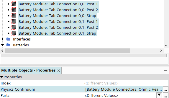
-
Expand the
Regions node and multi-select the six
Battery Module: Tab Connection nodes, and then set the
Physics Continuum to
Battery Module Connectors: Ohmic Heating.
- Save the simulation.