Pattern Offset Sketch
In sketch mode, the pattern offset tool allows you to create a succession of displaced sketch entities based on a single set of source entities.
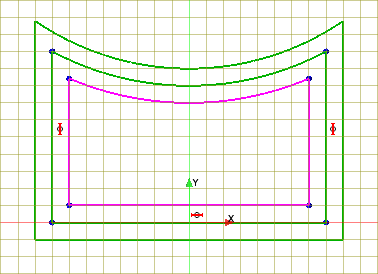
The image below shows the
base sketch highlighted in purple and the pattern offset result in green. Notice how
the base sketch is designed so that successive patterned offsets form a single
continuous path. After completing a sketch like this, you can sweep a feature
profile along the entire length of the path.

To create a pattern of sketch entities:
-
While in sketch mode, in the Sketch panel,
under the Sketch Operations group box, click
 (Pattern Offset Primitives).
- In the graphics window, select the desired entities for the base profile.
-
In the Offset Primitives group box, define
the properties that control the pattern (noting that design parameters can be
applied):
-
In Offset Direction, choose a direction for
the pattern:
- Outward—allows you to reproduce a
series of the base entities outwards.
- Inward—allows you to
reproduce a series of the base entities inwards.
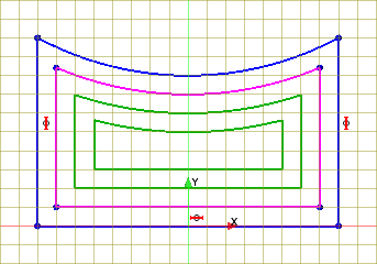
In an open sketch, the offset direction might not correspond to the result displayed in the 3D-CAD View scene. For example, the image below shows an example where the offset direction was set to Inwards but the pattern offset result appears outwards from the base selection sketch.
- Outward—allows you to reproduce a
series of the base entities outwards.
-
In Offset Direction, choose a direction for
the pattern:
- Click OK to complete the pattern offset and return to sketch mode.