Offsetting Sketch Entities
The offset tool enables you to uniformly displace sketch entities within the sketch plane.
When you activate the offset tool, you enter offset mode. Actions that you perform while in this mode are separate to the actions you perform in sketch mode. While in offset mode, you can undo and redo actions.

You can control the offset direction and the offset distance in each operation. The offset operation is compatible with both open and closed sketches, and projected entities from outside the active sketch. The original sketch entities can be converted to construction lines or left as they are.
To offset sketch entities:
-
While in sketch mode, in the
Sketch panel, under the
Sketch Operations group box, click
 (Offset Sketch Primitives).
-
In the graphics window, select the desired entities.
To select entities one-at-a-time, left click. To deselect entities, right-click on the entities. To select all connected entities, double-click.You can select multiple profiles for an offset in one offset operation.3D-CAD dynamically applies the current offset settings to entities as you choose them. If single selections complete a closed profile then the offset direction can switch depending on the settings.
-
In the
Offset Primitives group box, define the offset properties:
-
In
Offset Options, choose a direction for the offset:
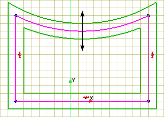
- Inward—Offsets the base entities inwards.
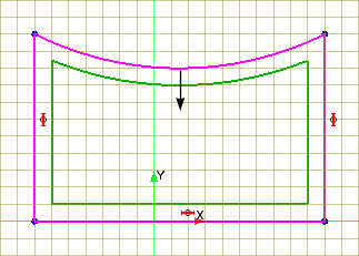
- Outward—Offsets the base entities outwards.
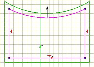
- Bi-directional—Offsets the base entities by the set amount, on both sides of the base sketch.
In a closed sketch, Inward always means inside the closed entities, while Outward always means outside the closed entities. In an open sketch, the offset direction is set according to the direction of the sketch (that is, the order in which you created the vertices). For example, consider the case that is shown below: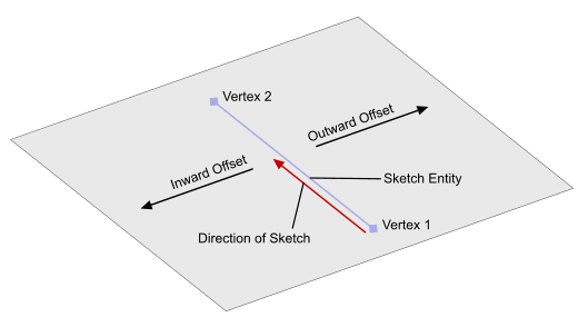
Creating an offset with the Offset Options property set to results in the offset being placed to the right of the sketch entity, as you look along the direction of the sketch. If the Offset Options property is set to , the offset appears on the left.
- Inward—Offsets the base entities inwards.
-
In the
Cap Options, choose how you want to fill any gaps between adjacent offset entities.
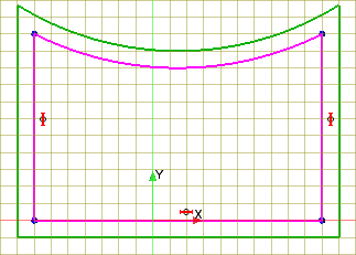
- Extensions—Extends the entities in the base sketch to the point where they intersect.
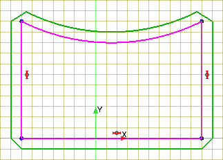
- Bevel Edges—Adds a bevelled edge between the adjacent offset entities.
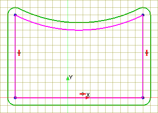
- Round Edges—Adds a round corner between the adjacent offset entities.
- Tangent Extensions—Extends the entities using an alternative method. Use this option when the
Extensions cap fails. When there is a small angle between entities, this option can extend the offset entities a large distance.
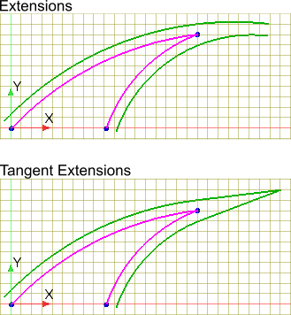
- Extensions—Extends the entities in the base sketch to the point where they intersect.
-
In
Offset Options, choose a direction for the offset:
-
Click
OK to complete the offset and return to sketch mode.
The sketch entities are offset using the settings you defined. A dimension is added to the sketch to constrain the offset. To make a change to the offset distance, double-click the dimension and enter a new value.