Faces, Edges, and Vertices in 3D-CAD
Faces
A face is a bounding surface of a body. Faces are created and updated automatically when you generate or modify a body. You can operate on faces through the
3D-CAD View window.

| Note | Double-clicking a face selects other faces that are connected and tangent to it. |
| Note | To select a chain of faces, select a face, press and hold the
Shift key, then select another face that belong to a set
of connected faces along the chain. All faces between the seed and the end face are
selected. You can use the Shift and click option for the
following scenarios:
|
You can give names to faces in 3D-CAD (these then appear in the folder within the body node). These surfaces then become boundaries when you assign the part to a region. When you convert a 3D-CAD model to geometry parts, the faces become surfaces.
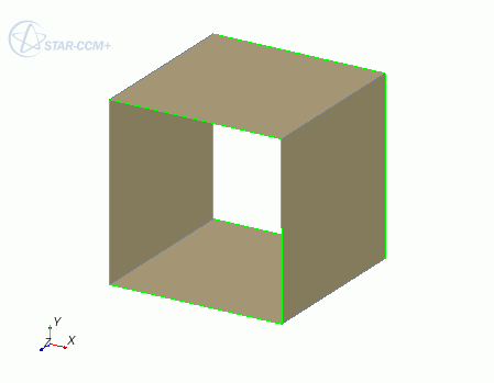
Edges
An edge is the line joining two adjacent faces
of a body. An edge is created and updated automatically when you generate or modify
a body. You can operate on edges through the 3D-CAD
View window. When you convert a 3D-CAD model to geometry parts, the
edges become curves.
| Note | Double-clicking an edge selects other edges that are connected and tangent to it. |
| Note | To select a chain of edges, select the start edge, press and hold the Shift key, then select an edge further along the chain. All edges between the start and finish edges are selected. If edge chains span multiple faces, and each edge in the chain shares two faces, then the edge chain based on tangency is selected. |
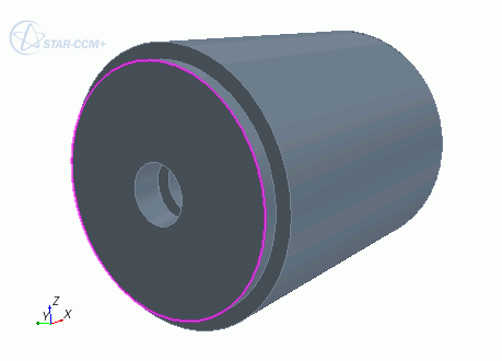
Free Edges
A free edge is an edge that lies on only one face. Free edges are indicated by a green color in the
3D-CAD View scene. If a free edge appears between two sheet bodies, this indicates that the sheet bodies are not connected. They can be sewn together if their edges coincide. If free edges form a closed loop, you can created a filled surface. You cannot use free edges with a Fillet or Chamfer operation.
| Note | Double-clicking a free edge selects all neighboring free edges that form a closed loop with that edge. |
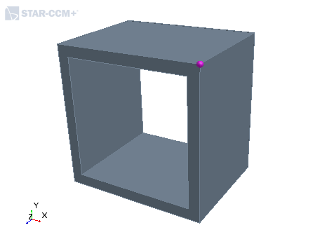
Vertices
A vertex is a point that lies at the end of an
edge. Typically, edges have two vertices, one on either end of the edge. Closed
edges, such as circles, have no vertices. You can interact with vertices on bodies
in the 3D-CAD View window. When you convert a
3D-CAD model to geometry parts, any vertices that you specifically named in the
3D-CAD model become available as points in the Points node
for each part. If you do not name any vertices then none are shown in the
Points node.