Moving Faces
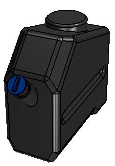
The Move Faces operation allows you to directly move a set of faces along linear, angular, or radial directions. 3D-CAD modifies adjacent faces and edges to compensate for the change of location.
To move a set of faces:
-
Before applying the Move Faces operation, use the
Reference Geometry tools to
create any supporting geometry that you require for the
move, such as a reference axis or coordinate system. For
more information, see Working with Reference Geometry in 3D-CAD.
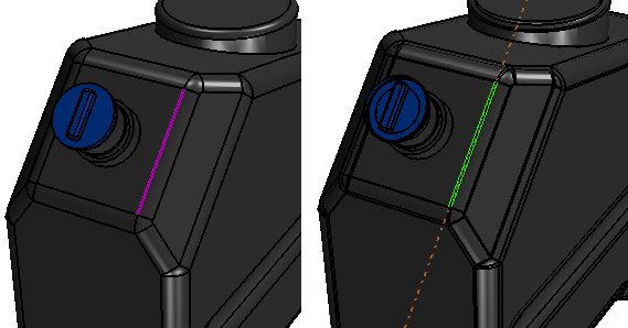
In the following example, an axis was created by selecting an edge next to the nozzle part and using the Axis From Linear Entity option.
-
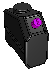
In the Graphics window, select
one or more faces that you wish to move. Right-click one of
the chosen faces and select Move
Face.
To save time in the selection process for repeated applications of this operation, you can construct a design filter that stores a selection of faces and reapply it each time. For more information, see Creating Design Filters.In the following example, the nozzle highlighted in purple was selected.
 The Move Face panel appears on the left of the Graphics window.
 -
If you want to move a set of faces along a specified axis, then
use the Reference Geometry tools to
create an axis. For more information, see Working with Reference Geometry in 3D-CAD.
In the following example, an axis was created by selecting an edge next to the nozzle part and using the Axis From Linear Entity option.
- In the Select Faces box, add any additional faces that you wish to move.
You can move faces in one of three directions:
- Linear: define a direction in a chosen coordinate system
- Angular: define an axis direction and origin about which to rotate the faces
- Radial: allows you to move faces in the radial direction
- To set the direction option, set Move Direction to Linear, Angular or Radial.
-
To complete the setup, set the required properties for the
chosen option. See Move Face Panel.
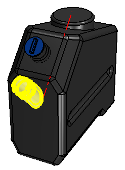
A preview of the operation is displayed in the 3D-CAD View scene.
-
Click OK to complete the feature.