Meshing the Smoothed Channel Surface
Now you replace the topology optimization domain geometry with the optimized channel geometry. Since you perform a flow analysis with the newly composed geometry, you mesh the topology optimized channel with the same number of prism layers and the same cell size as the inlet and outlet channels.
- In mesh operations, replace the Topology Optimization Domain with the smoothed TO Channel part:
- Select the node and set Input Parts by clicking
 (Custom Editor).
 - In the Automated Mesh - Input Parts dialog, deselect Topology Optimization Domain and select TO Channel instead, then click OK.
- Select the node and set Part Surfaces by clicking (Custom Editor).
- In the Disable Prisms - Part Surfaces dialog, expand the node and select Inlet Interface [Inlet /Topology Optimisation Domain] and Outlet Interface[Outlet /Topology Optimisation Domain], then click OK.
- Select the node and set Input Parts by clicking
- Assign the TO Channel part and its surfaces to the existing Topology Optimization region:
- Select the node and set Parts to TO Channel (while unselecting Topology Optimization Domain).
- Select the node and set Part Surfaces to Inlet Interface [Inlet /Topology Optimisation Domain].
- Select the node and set Part Surfaces to Outlet Interface [Outlet /Topology Optimisation Domain].
All other surfaces are automatically assigned. - Right-click the node and select Execute.
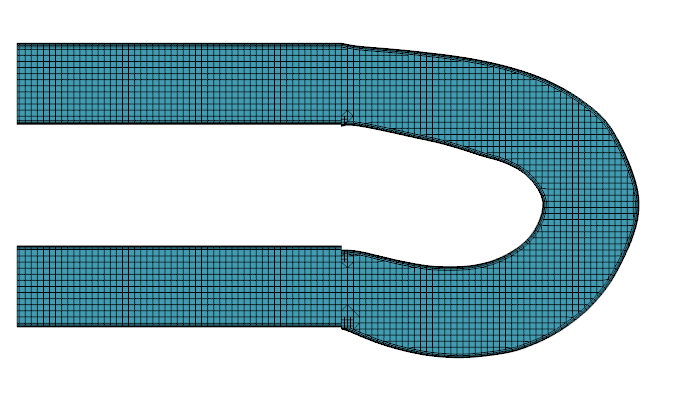
- To visualize the optimized channel mesh, create a new mesh scene.
- Save the simulation.