Extracting the Optimized Channel Surface
You extract the flow channel by creating an isosurface based on the inverted material indicator.
To extract the closed surface, Simcenter STAR-CCM+ collects all cells whose material indicator value is lower than the one you specify. In order to obtain the fluid material shape as an isosurface (as opposed to the solid material shape), you must use the inverse of the material indicator. Then, you extract this isosurface and create a geometry part from it.
To extract the optimized channel surface:
- Create a field function to calculate the inverse of the material indicator:
- Right-click the Derived Parts node and select .
-
In the Create Isosurface dialog:
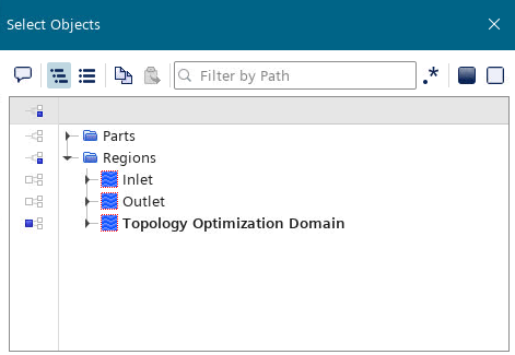
-
Set Parts to
Topology Optimization Domain, without the
boundaries.
-
Set Parts to
Topology Optimization Domain, without the
boundaries.
- Select the node and rename it to TO channel.
- Right-click the TO Channel node and select Extract Geometry Part.A TO Channel node is created under .
- Visualize the extracted surface:
- Select the node and set Parts to with all surfaces.
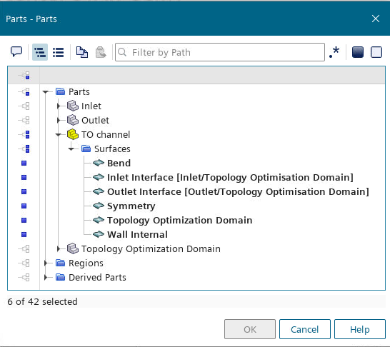
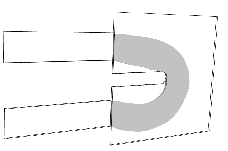
- Select the node and set Parts to with all surfaces.
- Save the simulation.