Creating Quadrilateral Meshes on Patches
This section describes how to create quadrilateral meshes on patches.
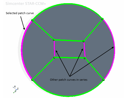
The Patch Mesh mode in the Edit panel is activated once the patch topology is complete, that is, all the patch curves are green. The patch mesh mode is used to define the mesh properties for the patch curves, including the number of divisions on each mesh curve, stretching distribution and patch mesh smoothing. Simcenter STAR-CCM+ applies the same mesh properties to a selected patch curve and its corresponding mapped curves. Mesh curves for which the mesh properties are defined appear in black. Once all curve series have a defined mesh distribution, Simcenter STAR-CCM+ automatically constructs and displays the mesh.
To create a patch mesh:
-
In the
Edit panel, select the Patch Mesh mode.
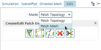
This mode contains the Mesh Properties box.
-
Select the patch curve for which you want to set mesh properties.
Simcenter STAR-CCM+ automatically selects all associated curves. Also, you can select more than one base curve, and Simcenter STAR-CCM+ automatically includes all the associated curves.
-
In the
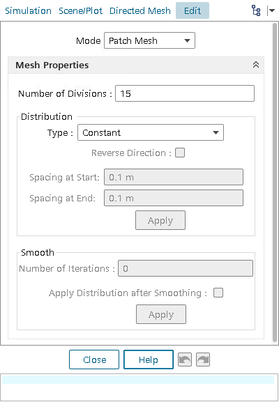
Mesh Properties box, set the
Number of Divisions to the desired mesh division amount.
After entering this value, press <Enter>.
-
In the
Distribution group box:
- Set the type of stretching for the mesh:
- Constant — The space between divisions is equal.
- One Sided Geometric — The space between divisions increases in one direction with a geometric function. Specify the spacing at the start of the stretching.
- One Sided Hyperbolic — The space between divisions increases in one direction with a hyperbolic function. Specify the spacing at the start of the stretching.
- Two Sided Hyperbolic — The space between divisions increases in both directions with a hyperbolic function. Specify the spacing at the start and end of the stretching.
- To reverse the stretching direction, activate the Reverse Direction checkbox.
- Click Apply to apply the distribution settings and generate the patch mesh.
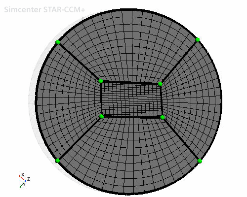
The direction of the stretching is shown in the Graphics window with a red arrow. The following is an example of using the distribution tool with the surface mesh.
- Set the type of stretching for the mesh:
-
In the
Smooth group box:
- To smooth the patch mesh when the patch topology is distorted or uneven, set the Number of Iterations.
- Activate the Apply Distribution after Smoothing box when the smoothing process distorts the selected stretching function.
- Click Apply to apply the smoothing settings and generate the patch mesh.
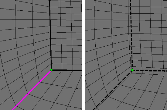
Simcenter STAR-CCM+ applies the smoothing after the patch mesh is generated. Patch vertices are moved from their original position so that they no longer lie on the patch curves. The original vertex locations of are still shown as are the original curves. Dashed lines represent the original curves.
| Note | If you increase the number of iterations, you achieve greater smoothing at a greater computational effort. The value of smoothing iterations is absolute and not cumulative from previous iteration values. |
In the following screenshot, the mesh on the right shows smoothing of the mesh on the left by moving the vertices.
If you want to change the patch layout after creating the patch mesh, change to Patch Topology mode. Any changes that you make to patch mesh properties are automatically applied to the mesh shown in the display.
A new Patch Mesh node is added under Source Meshes once you close the patch mesh Edit panel. If you right-click the new node and select Edit..., you can return to the Edit panel and review or edit the patch definition.
