Extend Solid Panel
The following controls are available in the Extend Solid panel.
General Settings
- Select Faces
- Specifies the faces to extend.
- Extend Direction
- Specifies how to define the extension. The available options are:
Normal Allows you to offset faces in the normal direction. 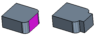
See Extension Options.
Linear Allows you to grow the solid along a line that you specify. The screenshot below shows an example using an existing reference axis. 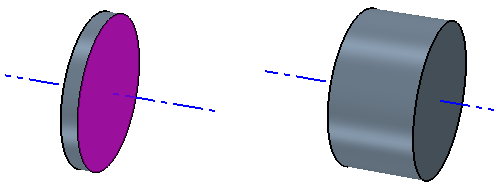
Angular Allows you to rotate a chosen face around an axis by a specified angle. 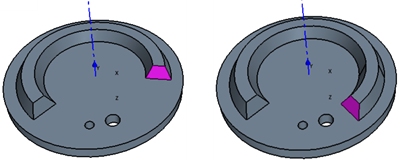
Note You can only specify an angle of below 180 degrees. Thicken Allows you to extend and stretch faces in the normal direction. 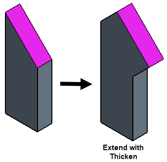
See Thicken Definition.
Extension Options
The following settings appear when you set Extend Direction to Normal. See General Settings.
- Method
- Defines how to set the end point of the extension.
Blind Extends the solid by the distance that you set in the Offset property. Up To Face Extends the solid to a target face. First click within the Target Face box, which activates selection, and then choose the target face in the Graphics window. The face that you select is displayed in the Target Face property. The target face must be large enough to cover the input face. 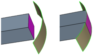
- Offset
- Set the distance by which a solid is extended in the normal direction.
- Tolerance
- Specifies the tolerance value for the operation. In some cases, the function may need to replace the geometry with a tolerant geometry. For example, in the case of a sheet body some edges at the boundary may have to be approximated by spline curves in order to create a boundary curve on the offset sheet. In such cases, the new geometry will have a tolerance less than or equal to the tolerance value specified.
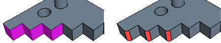
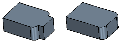
- Blends from Convex Edges
- When activated, rather than extend the faces on either side of the convex
edge uniformly, 3D-CAD creates a blend instead. A convex edge is an outer
edge formed by two adjacent faces. The blend radius value is the same as the
offset distance.
- Overflow Behavior
- When a solid extension passes over a hole in adjacent geometry, you can
define how the extension interacts with faces in the hole.
None 3D-CAD extends the solid without any interaction with adjacent topology. Default behavior. 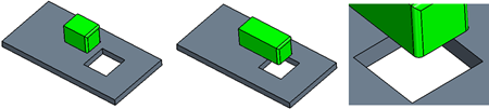
Grow Moving Face Extends the growing solid into holes within the adjacent geometry. 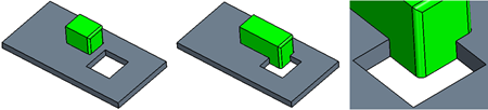
Grow Fixed Face Preserves the shape of adjacent holes within the growing solid. 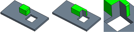
- Preserve Adjacent Blends
- When activated, allows you to
preserve the adjacent blends (fillets and chamfers). The extension is
limited to a linear direction.
Note With Preserve Adjacent Blends activated, if you set the Direction Type to Angular, Simcenter STAR-CCM+ ignores the specifed angle and extends the surface in a linear direction, normal to the face.
Linear and Angular Definition
The following settings appear when you set Extend Direction to Linear or Angular. See General Settings.
- Direction Type
- For Linear and Angular
extensions you can choose how to define the direction for the
extension.
Specified Allows you to specify a custom direction within a chosen coordinate system. Reference Axis Specifies the direction using a reference axis that you created. - Coordinate System Source
- Defines the custom direction for the projection using coordinate systems.
This option appears when you set Direction Type to
Specified.
Imported Uses an imported coordinate system. Select a coordinate system from the drop-down list that appears below this option. Reference Coordinate System Uses a reference coordinate system which you create. Click in the selection field that appears below this option and select the reference coordinate system in the 3D-CAD View scene. Axis Direction (X, Y, Z) Specifies the direction of the axis along which faces are extended. Enter the [X, Y, Z] components of the direction vector. Axis Position (X, Y, Z) o Specifies the origin of the axis around which faces are rotated (Angular) or moved (Linear). Enter the [X, Y, Z] components of the origin position or use the triad within the 3D-CAD View window.
Thicken Definition
The following settings appear when you set Extend Direction to Thicken.
- Offset
- Allows you to set a distance by which a solid is extended and stretched in the normal direction.