Remove Gashes
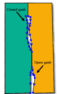
In 3D-CAD, a gash is a tear or disconnection between edges that ought to form a matching seam between two connected faces. Gashes generally appear as loops having a high aspect ratio but small area. If left untouched, gashes can affect the behavior of other features downstream in the 3D-CAD simulation tree.
As shown in the image
below, a gash can either be open or closed, and are expected to lie
between at least two distinct faces. Gashes are usually found on
parts imported from CAD systems where the native format permits
faces to fit together loosely.
For this feature to work as expected, the edges on either side of a gash must lie within the specified tolerance.
-
To launch the tool, do one of the following:
- Right-click the Features node in the 3D-CAD simulation tree and select .
- In the graphics window, right-click a body, face or edge and select .
The Remove Gashes panel appears on the left of the graphics window.
-
To select other bodies, body groups, or design filters, click
the
 (Object
Selector) icon on the right of the
selection box. Make further selections in the object
selection panel then click the icon again when done.
(Object
Selector) icon on the right of the
selection box. Make further selections in the object
selection panel then click the icon again when done.
- To remove one or all of your selections, right-click the selection in the list and choose the corresponding action.
- In the Gash Width box, enter the tolerance value (default 1.0E-4 m).
-
In the Gash Aspect Ratio box, enter the
value of the ratio (default 0.2).
Gash Aspect Ratio is the ratio of gash length to gash width.
- The Attempt to Form Solid option is activated by default and it attempts to form a solid body after executing the Remove Gashes operation.
-
Click OK.
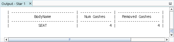
After the repair, a table appears in the Output window showing the end result of the operation.