Defining a Vector Warp Surface
A vector warp surface is a part that modifies input surface point coordinates by moving points along the selected vector multiplied by the scale factor.

To create a vector warp surface:
- Follow the general procedure that is outlined in the section, Defining Derived Parts General Workflow. Choose the menu option, .
- Specify the input parts and display option as described in the section, Defining Derived Parts General Workflow.
-
Complete the vector warp definition by specifying the following properties:
- Vector Field — select the
vector field function as the basis for the warp surface. The list of
available vector field functions depends on the physics models that you
selected.
You can specify the vector field using the Vector Field property, or the Vector group box in the in-place dialog.
-
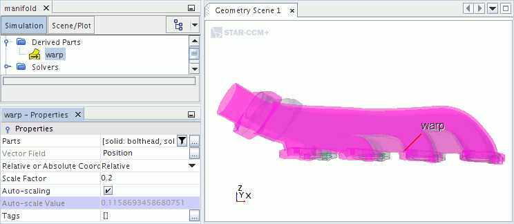
Scale Factor or Auto-scaling — control the factor by which the field is multiplied. These settings are available in the in-place dialog or the Properties window.
- To specify the scale factor manually, enter the fraction in the Scale Factor property.
- To have Simcenter STAR-CCM+ calculate the scale
factor automatically, activate the Auto-scaling property.
When you activate Auto-scaling, the numerical value of the scale factor is displayed in the Auto-scale Value property.
When you select the node of the warp surface with a scene open, the effect of the scale factor is displayed in a highlighted image of the derived part. The distortion that you see depends on whether you are using the auto-scale value or the manually specified scale factor.
- Vector Field — select the
vector field function as the basis for the warp surface. The list of
available vector field functions depends on the physics models that you
selected.