Defining an (m',theta) Warp
In Simcenter STAR-CCM+, the (m', theta) warp is used to present a flattened surface of revolution.
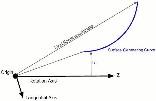
This derived part requires three pieces of information in its properties:
- The Origin of the axis of rotation
- The vector specifying the Rotation Axis
- A vector specifying the Tangential Axis—this axis is used to compute the angular coordinate.
The m’ coordinate is the arc length along the surface projected into the (z,r) plane and normalized by the local radius ([135]):
- is the axial coordinate along the axis of rotation.
- is the radial coordinate perpendicular to the axis of rotation.
Theta is calculated as the angle from the tangential axis:


The meridional coordinate is defined as:
The Tangential Axis property does not have to be orthogonal to the Rotation Axis since only the component orthogonal to the rotation axis is used.

- The rotation axis is [0, 0, 1] (aligned with the z-axis).
- The origin is upstream of the surface at [0, 0, -10].
- The tangential axis, [0, 1, 0], is orthogonal to the rotation axis.
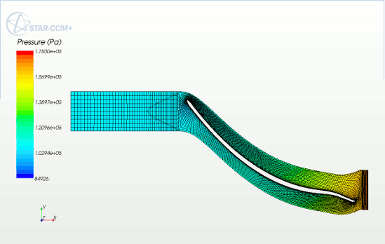
- The following screenshot shows the view down the z-axis. The derived part maps the m’ coordinate to x and the theta coordinate to y.

The derived part is computed by determining the generating curve from the part. So if there are multiple parts in a displayer, they must form a continuous surface for the derived part to be valid.
To create an (m',theta) Warp:
-
Right-click the
Derived Parts node and select
.
An (m’, theta) warp part appears in the simulation tree immediately.
-
In the
Properties window, specify the input parts, the
Rotation Axis and its
Origin, and the
Tangential Axis.
For more information on the available properties, see (m',theta) Warp Properties.