Defining a Separation/Attachment Line
Separation/attachment lines are lines along which flow separates from or attaches to a surface.
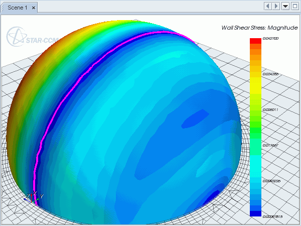
The following image shows how
Simcenter STAR-CCM+ uses the wall shear stress vector field to identify separation lines (the line is shown in magenta for clarity). However, several other parameters are used to identify a separation line, and you can also use cell relative velocity as the vector field. The cell relative velocity is the fluid flow velocity at the cell centroid relative to the cell centroid due to motion.


To create a separation/attachment line:
- Follow the general procedure outlined in the section, Defining Derived Parts General Workflow. Choose the menu option, .
-
Under
Input Parts, specify the input boundaries that are used to generate the separation/attachment line. Typically, this part is a no-slip wall, over which fluid is flowing. Also, specify a display option.
For more information on specifying input parts and display options, see Defining Derived Parts General Workflow
-
Complete the separation/attachment line definition by specifying the following properties:
- Vector Field — select the vector field used by the algorithm to calculate the separation/attachment line. This must be either wall shear stress or cell relative velocity. If you select another vector field, a separation/attachment line is still created, but the result will be invalid.
- Display Attachment Lines and Display Separation Lines — specify whether attachment or separation lines are included in the derived part. Attachment occurs when flow meets a wall boundary and flows along the surface. Separation occurs when flow leaves the surface.
- Line Strength — this property does not represent a physical quantity, but is used by the code to filter out weak results (that is, lines that do not represent a strong flow separation).
- Minimum Line Length — specify a minimum length for the derived part lines. The lines that are shorter than the minimum length are excluded.
- Line Quality — specify the angle between the separation/attachment line and the flow vector, which filters lines from the derived part that are at a large angle to the flow.
You can set all properties in either the in-place dialog or the Properties window.
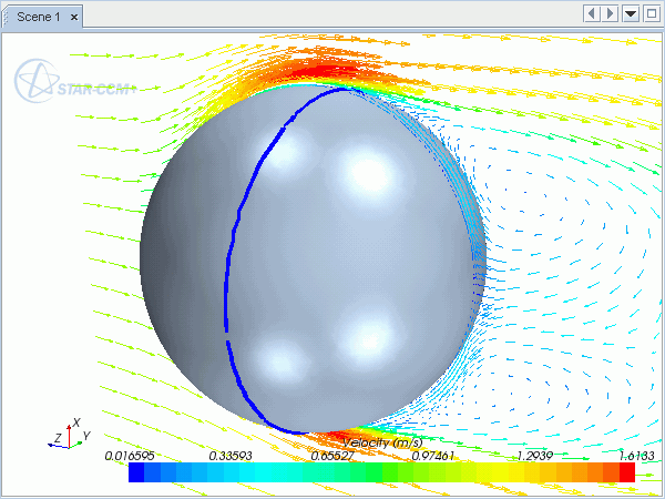
For more information on the available properties, see Separation/Attachment Line Properties.Once you have extracted a separation/attachment line, you can display it in a graphics scene with a scalar color, if desired. You can also use it as the input part for a streamline displayer, so that the streamlines begin along the separation line.The following image shows a separation line that is displayed using a streamline displayer. The thickness of the line has been increased to make it more prominent on the geometry surface. The velocity vectors illustrate where flow separation occurs, which matches the separation line location.
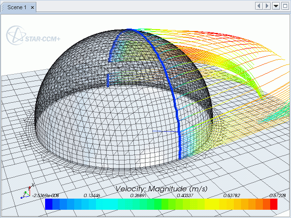
You can also use separation/attachment lines as a seed part for a streamline derived part. This can be used to analyze the flow path after the point of flow separation, which is illustrated in the example below.