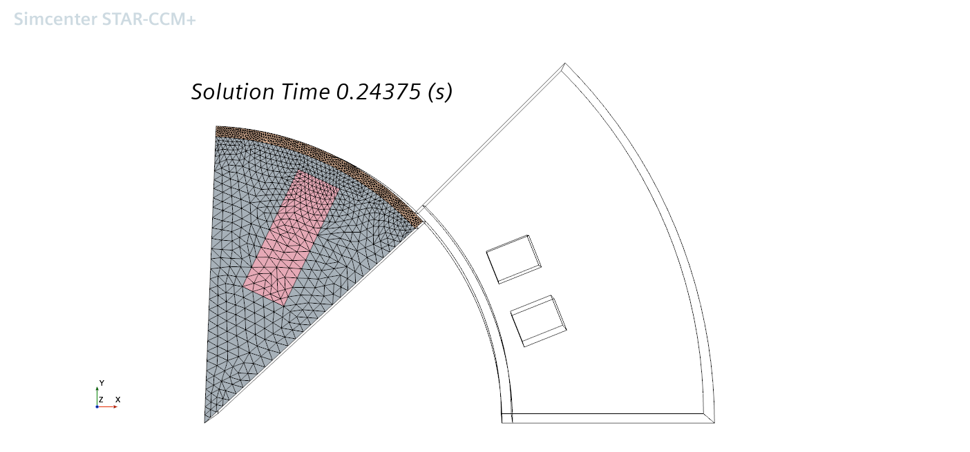
Defining a Subdivision Part
To improve visualization of finite element-based field functions, for example those arising in electromagnetics, you can subdivide the mesh.
Subdivision can increase the quality of the post-processing, offering smoother and clearer visualization without affecting solver performance. Moreover, the subdivision not only helps improve the visual smoothness of the solution, but it also gives more face/vertices on which to evaluate reports. For example, more accurate Minimum and Maximum values can be captured, as well as general reports such as surface integrals that would benefit from using more elements or nodes. However, consider the following:
- The subdivision part supports only surface and line inputs, but you can also use other derived parts as inputs.
- When using a mesh that originated from a curved surface, the subdivision does not follow the curvature - the individual cells are divided linearly in their plane. This approach may have effect on accuracy of reports computed on the surface.
To create a subdivision part:
- Follow the general procedure outlined in the section, Defining Derived Parts General Workflow. Choose the menu option, .
- Specify the input parts and display option as described in the section, Defining Derived Parts General Workflow.
- Complete the subdivision part definition by specifying the Subdivision Mode property, which lets you determine whether to specify the subdivision with a base level (integer number of subdivisions) or a field function. For details, see Subdivision Part Properties.
