Specific Derived Parts Reference
- Implicit Section Properties and Implicit Section Right-Click Actions
- Isosurface Properties
- Threshold Properties
- Scalar Warp Properties
- Vector Warp Properties
- Streamline and Constrained Streamline Properties
- (m', theta) Warp Properties
- Separation/Attachment Line Properties
- Vortex Core Properties
- Average Surface Properties
- Average Profile Properties
- Subdivision Part Properties
- Point Probe Properties
- Line Probe Properties
- Presentation Grid Properties
- Arbitrary Probe Properties and Actions
- Resampled Volume Properties
Implicit Section Properties
- Section Mode
- Defines whether the part includes a single or multiple sections.
- Input Mode
- Line Section: specifies two coordinates with one of two modes.
- Displayed Index
- Controls the display of sections when a multiple mode is used. Enter either a positive integer to display the corresponding section, or a value of -1 to display all sections.
- Infinite Line
- Line Section: when activated, projects an infinite line that cuts through the entire domain. Otherwise the line is a segment defined by the origin-direction or point-to-point input.
- Origin
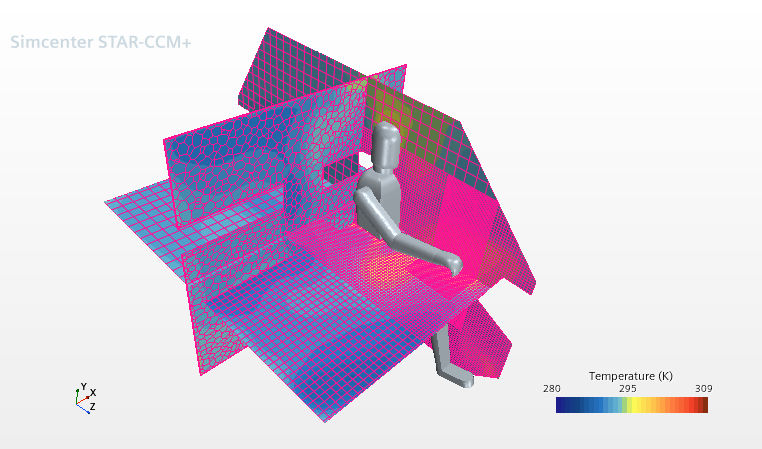
- Plane Section/Constrained Plane Section: a Cartesian position vector that defines the origin of the plane. You can include units.
- Normal
- Plane Section/Constrained Plane Section: a Cartesian position vector that defines the second point through which the plane normal passes. The first point is the origin of the selected Coordinate System. You can include units.
- Orientation
- Cylinder Section: a Cartesian position vector that defines the second point through which the cylinder axis passes. The first point is the origin of the selected Coordinate System. You can include units.
- Radius
- Cylinder Section/Sphere Section: the radius of the cylinder or sphere section. You can include units.
- Surface Input Option
- Arbitrary Section: Specifies the source of the input geometry. The available options are File, that allows you to import arbitrary STL data, and Part Surfaces, that allows you to select one or more of the existing CAD part surfaces in the simulation.
- Extract Approximate Faces
- Arbitrary Section: when deactivated, the arbitrary section retains its original surface geometry and slices through the sample region. When activated, Simcenter STAR-CCM+ creates an approximation of the surface that maps to the closest mesh cell faces. This option is faster because it does not have to compute the intersection between the section’s surface geometry and the part or region.
- Flip Orientation
- Arbitrary Section: when activated, Simcenter STAR-CCM+ reverses the directions of the normal vectors of the sample surface faces. The results become evident in reporting for relevant quantities such as mass flux. When deactivated, the face normals are right-hand oriented with respect to the counter-clockwise winding order of the original triangles in the section geometry.
Implicit Section Right-Click Actions
- Re-Import Data...
- Constrained Plane: Imports data from either an STL or VTK file. This option can be used to replace data that are imported during the creation of this derived part.
- Export Loop...
- Constrained Plane or Arbitrary: Exports the polygon bounding the constrained plane section to an external an STL file.
Isosurface Properties
- Scalar Field
- Specifies the scalar field function upon which the isosurface is based. See Field Functions.
- Mode
- Specifies whether a single isosurface or multiple isosurfaces are created.
Threshold Properties
- Scalar Field
- Specifies the field function that is used to determine the threshold range. See Field Functions.
- Range
- Specifies the minimum and maximum of the threshold range.
- Mode
- Specifies how to set the threshold with respect to the specified scalar range:
- Between: the threshold encompasses cells with all values between the minimum and the maximum of the Range.
- Above Max: the threshold encompasses cells with values greater than the maximum of the Range.
- Below Min: the threshold encompasses cells with values less than the minimum of the Range.
- Outside: the threshold encompasses cells with values less than the minimum and greater than the maximum of the Range.
Scalar Warp Properties
- Scalar Field
- Specifies the scalar field function upon which the warp surface is based. See Field Functions.
- Scale Factor
- Specifies the scale factor for the warp surface.
Vector Warp Properties
- Vector Field
- Specifies the vector field function upon which the warp surface is based. See Field Functions.
- Relative or Absolute Coordinates
- Lets you control the "base" vector, the original position or the updated position:
- Relative: refers to the updated position.
- Absolute: refers to the original position.
- Scale Factor
- Specifies the scale factor for the warp surface.
- Auto-scaling
- When activated, automatically calculates the scale factor based on the sizes of the vector warp and its input parts.
- Auto-scale Value
- When Auto-scaling is activated, displays the automatically calculated value of the scale factor. Otherwise the displayed value is 0.0.
Streamline and Constrained Streamline Properties
- Vector Field
- Selects the type of vector field function to show, such as velocity or flow direction. See Field Functions.
- Seed Type
- Specifies how the seed point is clustered and defined:
- Integration Solver
- Allows you to select the Runge-Kutta integration solver. The available options are 2nd-Order RK, 4th-Order RK, and Adaptive-Step RK, which activate corresponding child nodes: 2nd Order Integrator, 4th Order Integrator, and Adaptive Integrator. You can define the integration process by setting the properties of the integrator child nodes:
- Integration Direction: specifies the direction of integration from the seed location. The available options are:
- Forward: the integration proceeds in the forward direction (for instance with the flow if velocity is the vector field).
- Backward: the integration proceeds in the backward direction (for instance against the flow if velocity is the vector field).
- Both: the integration proceeds both forward and backward from the seed location.
- Initial Integration Step: specifies the initial integration step size in units of cell length. Reducing the value creates a higher resolution for the streamlines.
- Maximum Error: the maximum allowable error in integration before step size is adjusted.
- Maximum Integration Step: specifies the maximum integration step size in units of cell length.
- Maximum Propagation: specifies the maximum length of the streamlines in units of cell length.
- Max Steps: specifies the maximum number of integration steps.
- Integration Direction: specifies the direction of integration from the seed location. The available options are:
- Rotation Scale
- The scale factor for twist.
- Wall Treatment
When activated, Simcenter STAR-CCM+ forces the streamlines to be wall-parallel at boundaries. This option is activated by default.
(m', theta) Warp Properties
- Rotation Origin
- Sets the rotation origin for an (m', theta) warp.
- Rotation Axis
- Sets the rotation axis for an (m', theta) warp.
- Tangential Axis
- Sets the tangential axis for an (m’, theta) warp.
Separation/Attachment Line Properties
- Display Attachment Lines
- Toggles whether lines displaying flow attachment are displayed or not.
- Display Separation Lines
- Toggles whether lines displaying flow separation are displayed or not.
- Vector Field
- Specifies the vector field that is used by the algorithm to extract the separation/attachment line. This must be set to wall shear stress or cell relative velocity. If you use a different three-dimensional vector field, it does not produce valid results.
- Line Quality
- Filters lines where the angle between the extracted separation/attachment line and the flow vector are below the user-defined value. The quality is entered on a scale of 0.0 to 90.0 degrees.
- Line Strength
- Sets the strength of the separation/attachment. This setting is used to filter out weak results. Line strength is not a physical quantity, but a filtering property. The strength is entered on a scale of 0–1, where 0 includes all separation/attachments, and 1 includes only the strongest results.
- Minimum Line Length
- Sets the minimum separation/attachment line length. Separation/attachment lines which are shorter than this value are eliminated.
Vortex Core Properties
- Vortex Quality
- Computes the angle between the extracted core line and the velocity vector at this position. Small angles mean high quality; this may not apply to all simulation data.
- Vortex Strength
- Sets the strength of the rotational motion. This setting is used to filter out weak vortices.
- Minimum Core Length
- Sets the minimum length of a line to be used by a vortex core. Below this setting, the core lines are eliminated.
- Vector Field
- Specifies the vector field that is used by the algorithm to extract the vortex core. This must be set to velocity. If you use a different three-dimensional vector field, this would not lead to a valid result.
Average Surface Properties
- Parameterization
- Selects an axisymmetric parameterization that includes the input parts chosen for this derived part. Any axisymmetric parameterization that does not include all the input parts chosen for the derived part does not appear in the drop-down list.
- Weighting
- Determines whether and how to apply weighting as follows:
- None—no additional functions are multiplied by the cell field function value; regardless of weight function, the line segment through the cell is used.
The closest equivalent is a Riemann sum, where each cell contributes the cell value multiplied by the length of the bin-center line segment. The bin-center line segment has a constant span-wise and flow-wise coordinate located at the geometric center of the bin and runs in the circumferential direction.
- Scalar Function—multiplies the cell scalar of your choice by the cell field function value when computing the average.
- Mass—multiplies the cell field function value by cell mass when computing the average. For this option to be available, the field function Density must be present in the simulation.
- Mass Flow—multiplies the cell field function value by the mass flow rate in the meridional direction (primary flow direction) when computing the average. For this option to be available, the field functions Density and Cell Relative Velocity must be present in the simulation.
- None—no additional functions are multiplied by the cell field function value; regardless of weight function, the line segment through the cell is used.
Average Profile Properties
- Parameterization
- Selects an axisymmetric parameterization that includes the input parts chosen for this derived part.
- Binning Mode
- Determines how to generate the 1D bins:
- Equal distance—you specify the number of bins, and all bins are of equal size.
- Mesh resolved—the bin size adjusts to half the local mesh size.
- Functions
- Selects a field function with which to map back to the input surfaces. This property lets you produce a 1D data set of the circumferentially averaged solution on a given plane or surface. When you select an existing field function, for example Axial Velocity, for this property, a new field function appears, Average Profile: Axial Velocity. The circumferentially averaged field can be displayed on a 2D surface in the same shape as the input surface in order to examine it in context with the 3D model.
- Weighting Mode
- Determines whether and how to apply weighting as follows:
- Area—uses surface area only.
For a field f, the averaged f is defined as:
Where subscript i is the bin index and c is the face index. is the area of face c that overlaps within the ith bin.
- Area-Adjusted Scalar Function—multiplies the face area and a scalar of your choice by the face field function value when computing the average.
Where is the chosen scalar field.
- Mass Flow—multiplies the
face field function value by the mass flow rate in the meridional
direction (primary flow direction) when computing the
average.
Where is the fluid density, is the fluid velocity at face c, and is the directed area vector. In the context of turbomachinery, would point along the u (streamwise/meridional) coordinate direction. Hence the averaging formula is given by:
- Area—uses surface area only.
For a field f, the averaged f is defined as:
Subdivision Part Properties
- Subdivision Mode
- Selects the method by which to subdivide meshes.
Point Probe Properties
- Point
- Specifies a Cartesian position vector that defines the location of the point.
- Follow Motion
- Controls whether the point probe moves together with a moving mesh or not. When activated, the point probe attaches itself to the moving mesh and keeps track of the cell it is in and its relative position within that cell. Every time the mesh moves, the point checks its position to ensure that it is inside the correct cell and in the correct position within that cell. When deactivated, the point probe remains stationary (assuming that its assigned coordinate system is not moving). This option works with all types of motion.
- Highlight Input Coordinates
- When activated, highlights the original coordinates that you specified, regardless of what happens to the corresponding point probe after intersection. For example, if a given point probe only has a volumetric region as its input part, that probe would exist only if it lies within the region. Otherwise it is invisible when Highlight Input Coordinates is deactivated.
Line Probe Properties
- Point 1
- Specifies a Cartesian position vector defining one end of the line.
- Point 2
- Specifies a Cartesian position vector defining the other end of the line.
- Resolution
- Specifies the number of evenly spaced segments along the line. The actual number of points in the probe is one greater than the number of segments; fewer points may be generated if part of the probe lies outside the model geometry.
Presentation Grid Properties

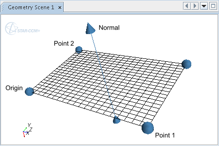
- Normal
- Specifies the vector passing through the center of the presentation grid at a right-angle. Entering a new value for Normal automatically adjusts the values for Point 1, Point 2 and Origin, in order to define a grid that matches the current properties.. Use this property as an alternative to Point 1 and Point 2 to define the plane. You can include units in the entry, or select the units in the dialog that is activated by clicking
 (Custom Editor).
 - Origin
- Specifies the lower-left corner on the presentation grid relative to the selected coordinate system. Entering a new value for Origin automatically adjusts the Normal, in order to define a grid that matches the current properties. You can include units in the entry, or select the units in the dialog that is activated by clicking
 (Custom Editor).
 - Point 1
- Specifies the lower-right corner on the presentation grid, relative to the selected coordinate system. Entering a value for Point 1 automatically adjusts the Normal, in order to define a grid that matches the current properties. Use this property along with Point 2 as an alternative to Normal to define the plane. You can include units in the entry, or select the units in the dialog that is activated by clicking
 (Custom Editor).
 - Point 2
- Specifies the upper-left corner on the presentation grid, relative to the selected coordinate system. Entering a new value for Point 2 automatically adjusts the Normal, in order to define a grid that matches the current properties. Use this property along with Point 1 as an alternative to Normal to define the plane. You can include units in the entry, or select the units in the dialog that is activated by clicking
 (Custom Editor).
 - X Resolution
- Specifies the number of intervals between data points along the x-axis (that is, Number of Data Points = X Resolution + 1). The x-axis is the axis between the Origin and Point 1.
- Y Resolution
- Specifies the number of intervals between data points along the y-axis. The y-axis is the axis between the Origin and Point 2.
| Note | The Normal, Point 1, Point 2 and Origin properties override one another according to the most recently entered value. |
Arbitrary Probe Properties and Actions
- Surface Input Option
- Specifies the source of the input geometry. The available options are:
- File: allows you to read in points from a STL or VTK file.
- Part Surfaces: allows you to select one or more CAD part surfaces from which to extract the sample points.
- Re-Import Data... (right-click action)
- Allows you to load new sample points from an STL or VTK file.
Resampled Volume Properties
- Origin
- A Cartesian position vector that defines the origin of the resampled volume. You can include units in the entry, or select the units in the dialog that is activated by clicking
 (Custom Editor).
 - Rotation Axis
- Sets the rotation axis for the resampled volume.
- Size
- Sets the size of the resampled volume in three dimensions. You can include units in the entry, or select the units in the dialog that is activated by clicking
 (Custom Editor).
 - Rotation Angle
- Specifies the angle of rotation along the specified rotation axis in radians.
- Cell Size to Voxel Ratio
- Determines the discretization
of the resulting structured voxel mesh. Increasing this value always
increases the number of voxel cells. Based on two refinement metrics this
value represents the ratio between the size of volume mesh cells and size of
voxel cells. The size is defined by the chosen refinement metric:
- Values significantly lower than 1 lead to a down-sampling when comparing the number of volume mesh cells and number of voxel cells.
- Values around 1 lead to a more refined voxel mesh with a greater number of voxel cells.
- Values significantly above 1 are not recommended, because they can lead to unwanted over-refinement.
- Refinement Metric
- Allows an adjustment in the definition of the Cell Size to Voxel Ratio setting:
- Surface: uses the ratio between the surface of a volume mesh cell and the surface of a voxel cell.
- Diagonal:
uses the diagonal of a hexahedral bounding box around a volume mesh
cell.
This option, which is the default, reduces the amount of voxels generated in portions of a model that contain prism layers and is therefore preferable to the Surface option.
- Minimum Voxel Size
- Sets the minimum size of a voxel cell. The minimum size is based on edge-length of the cubic voxel cell. No voxel with a length smaller than this value is created. The Minimum Voxel Size has precedence over the Cell Size to Voxel Ratio. For data structural reasons the minimal number of voxel cells cannot be smaller than 4913 voxels.
Resampled Volume Settings Properties
- Rendering Mode
- Allows you to select a mode of rendering. The following options are available:
- Volume - Every scalar sample value is mapped to the displayer opacity plus color, and is then attenuated along the view direction.
- Isosurface - Allows you to choose between single or multiple surfaces. Activates a Isosurface Mode sub-node.
- Maximum Opacity Projection - A transparent mode with high contrast to highlight volume areas that contain scalars with high opacity. An example is when velocity magnitude is mapped to a high-pass color map. The transparent mode reveals additional points of interest, regardless of the opacity attenuation which is depending on the viewpoint. However, the projective nature of this mode removes clues for depth perception.
- Plane Section - Allows you
to incorporate interactive plane sections in the volume rendering.
Activates a Plane Sections sub-node.
If you activate the Display Mesh property of the displayer that includes these section planes, the planes show the mesh of the resampled volume itself, letting you view the size of individual voxels that are used to resample a field.

To display the original grid, use a plane section derived part (instead of a resampled volume derived part).
- Lighting Mode
- Allows you to apply displayer
lighting to the volume rendering. The primary application for the Local
Lighting mode is when the Rendering Mode property
is set to Isosurface. In the Isosurface mode,
standard lighting is applied to the isosurface exactly as if it were a
proper surface. Additionally, local lighting is used in the Volume rendering
mode for a more “surface-like” image without actually reverting to simple
surfaces.
- None - Does not use displayer lighting.
- Local
Lighting - Applies the settings of the
displayer surface lighting. The advantage of this technique is that
details in the scalar field can be discerned more easily in many
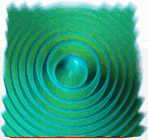
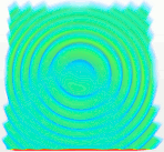
cases. The following Marschner-Lobb examples of volume rendering
illustrate the benefit of local lighting.
- Local
lighting:

- No
local lighting:

- Local
lighting:
- Automatic - By default, deactivates lighting effects for Volume and Maximum Opacity Projection rendering modes, and activates lighting effects for Isosurface and Plane Section rendering modes.
- Quality
- Determines how accurately the resampled volume is processed during ray-casting.
Volume Rendered Isosurface Mode Properties
- Isosurface Mode
- The mode for isosurface volume rendering, specifying whether a single surface or multiple surfaces are created.
- Single - Uses one surface (default).
- Multiple (range) - Selects a range technique for creating multiple surfaces.
- Multiple (arbitrary) - Selects an arbitrary technique for creating multiple surfaces.
Volume Rendered Plane Sections Object Properties
The Plane Sections node contains the volume rendered plane section objects in the displayer. Use the properties of any of these objects to activate it, deactivate it, and specify its coordinates.
- Origin
- Sets x, y, and z coordinates for the origin of the plane.
- Normal
- Sets x, y, and z coordinates for the second point of the plane.
- Enabled
- Uses a checkbox to turn the clip plane on or off.