Surface Extruder
The surface extruder extends the edges of the input surface to form the bounding surfaces of the extruded region. You specify the extrusion distance in the surface extruder operation.
For information on how to use the extruder mesher in parts, see Using the Extruder in Parts.
Surface Extruder Properties
| Parameter | Description | |
|---|---|---|
| Grid Type | Specifies the type of extrusion to generate at a corner. You cannot generate a combination of H-Grid and O-Grid extrusions in the same operation. | |
| O Grid | For the O
Grid option, which is on by default, the surface
extruder computes the average normal (found using Singular Value
Decomposition) at the common vertex between adjacent connected
part surfaces and generates layers along the average
normal. |
|
| H Grid | For the H
Grid option, the surface extruder generates mesh
portions iteratively for part surfaces that are not co-planar.
That is, around an edge, the surface extruder uses the output of
the first mesh extruded mesh portion as input to the second mesh
portion. The H Grid type is generated only between the part surfaces selected as input to the surface extruder operation.  |
|
| Input Parts | Specifies the part that acts as the source for the surface extruder. | |
| Input Part Surfaces | Specifies the surface to be extruded. The input surfaces are projected a specified distance away from the original surface. The edges of the input surfaces are extruded to form the sides of the extruded region. | |
| Create New Part | Specifies what parts are created as a result of the surface extrude operation. Single New Part creates a single part for the surface extruder, even if multiple inputs are selected. Per Part creates separate parts for each individual input parts. Per Part Surface creates separate parts for each individual input part surfaces. | |
| Output Part Surfaces | Specifies how to pre-execute part surfaces in the output part. All Pertinent Sides creates one side part surface in the extruded part for every side part surface of the input parts. Single Side creates a single side part surface for all input sides. | |
Surface Extruder Expert Properties
| Parameter | Description |
|---|---|
| Create Internal Surface(s) | Provides the option to create internal channels using the cell
faces generated by the volume extruder. The channels are formed
by duplicating the internal cell faces in the extruded volume
mesh. None creates no internal surfaces. One Surface creates a single surface from each extruded internal cell face. Two Surfaces creates two identical surfaces for each extruded internal cell face. If the input part surface is a wall boundary, cross flow is not allowed between the channels. This functionality is useful when performing CFD analyses of heat exchangers which model hot and cold fluid streams through channels in a porous region between periodic interfaces. |
Surface Extruder Controls
| Parameter | Description |
|---|---|
| Direction Mode | Specifies the method to
use when defining the direction and distance of the extrusion.
Surface Normal extrudes the region
normal to the input part surface. For cases where the input part
surface is not completely planar (jagged edges, bumpy surface)
and a relatively long extrusion distance is required, select
Average Normal.
Specified extrudes the region in a
specified direction. The image below shows the results of the
Surface Extrude for a jagged surface with Surface
Normal and Average
Normal respectively. 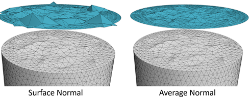 |
 Extrusion Distance
|
Specifies the distance of the extrusion when you set Direction Mode to Surface Normal or Average Normal. |
|
Specified
|
Specifies the coordinate system and direction when you set Direction Mode to Specified. Coordinate System specifies the coordinate system to use for the extrusion direction. You can use custom coordinate systems. Distance specifies the magnitude of the extrusion, where each component is the displacement along the corresponding axis of the chosen coordinate system. |