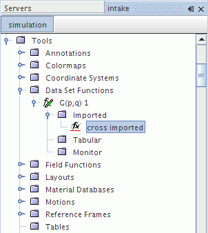
Derived Cross Imported Model Data Sets
Derived cross imported model data sets hold correlations from two input signals.

This object cannot be deleted while a link is in place from derived data sets in a plot. This object shares pop-up menu items with other derived data sets.
The function definition requires:
- Importing the surface from an existing .trn or .simh file.
- Extracting a field function from that surface.
- Selecting a point part as a probe.
The above quantities can be specified using the properties of this object. If the Update Active property is activated, the point-to-point time Fourier transform or the point-to-point time correlation is calculated after the last property assignment. Alternatively, you can calculate the transform by right-clicking the node and selecting Update Output, irrespective of the state of the Update Active property.
Derived cross imported model data sets are not updated automatically when you change a part position. A modified part can have many associated derived cross imported model data sets. An automatic update would take some time and cause the Simcenter STAR-CCM+ user interface to lock until the process is complete.
When any part is modified, all of its derived cross imported model data sets are shown as requiring an update. The Update Active property for the affected derived cross imported model data sets is automatically deactivated.
- To update a derived cross imported model data set, do one of the following:
- In the Properties window, manually activate the Update Active property.
- Right-click the derived cross imported model data set and then click .
Cross Imported Properties
|
Update Active |
When this property is activated, the update is active for the imported point. When a part is modified, this property is automatically deactivated for all of the affected derived cross imported model data sets. |
|
|
X Units |
Displays the calculated units for the x-axis data. |
|
|
Y Units |
Displays the calculated units for the y-axis data. |
|
|
Field Function 1 |
Defines the field function that is extracted. Only field functions added by a .trn or .simh file can be selected. |
|
|
Data Surfaces 1 |
Defines the surfaces from which data is extracted. Only surfaces from a .trn or .simh file can be selected. |
|
|
Point Part 1 |
Defines the point on the surface where data is extracted. This point is the point on the surface closest to a selected point derived part. |
|
|
RMS Magnitude |
Reports the size of the root mean square value of the signal after adjustment for signal processing. That is, the mean of the signal is removed before computing the RMS. The RMS is the square root of the average of the squares of the data. This adjusted RMS can be understood as the energy in a signal. Read only. | |
|
RMS Units |
Displays the calculated units for the RMS. | |
|
Representation |
Selects a representation to indicate data from a .trn or .simh file. | |
|
Field Function 2 |
Defines the field function that is extracted. Only field functions added by a .trn or .simh file can be selected. |
|
|
Data Surfaces 2 |
Defines the surfaces from which data is extracted. Only surfaces from a .trn or .simh file can be selected. |
|
|
Point Part 2 |
Defines the point on the surface where data is extracted. This point is the point on the surface closest to a selected point derived part. |
|