Defining a Presentation Grid
The presentation grid part samples data from regularly spaced intervals on a finite plane in a region.

To create a presentation grid:
- Follow the general procedure outlined in the section, Defining Derived Parts General Workflow. Choose the menu option,
-
Specify the input parts, display option, and coordinate system as described in the section,
Defining Derived Parts General Workflow.
If a presentation grid spans two parts, selecting only one part as input part will ignore all data points in the second part.
-
Complete the presentation grid definition by setting the following properties:
- In the in-place dialog, position the plane by either setting the
Center and
Normal properties, or by using the plane tool in the scene display. See
Using the Explicit Plane Tool.
You can activate the Snap To Part option to position the plane along a part (this action is essentially snapping to the bounding box of the part).
Simcenter STAR-CCM+ automatically calculates the coordinates of the origin, point 1, and point 2 based on the plane position.
- Alternatively, specify the x, y, and z coordinates of the Origin in the Properties window. Then, specify the normal or the coordinates of Point 1 and Point 2.
The coordinates are relative to the specified coordinate system. If using a cylindrical or spherical coordinate system, the units for position vectors update accordingly.Note Using a cylindrical or spherical coordinate system does not create a cylindrical or spherical presentation grid. 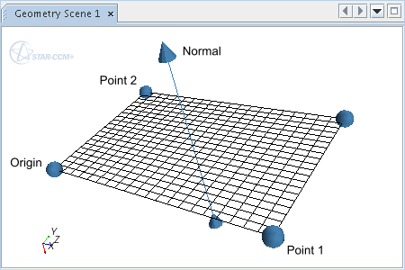
- In the in-place dialog, position the plane by either setting the
Center and
Normal properties, or by using the plane tool in the scene display. See
Using the Explicit Plane Tool.
-
Specify the
X Resolution and the
Y Resolution in the
Properties window or the in-place dialog.
For example, the following grid has an X Resolution of 5 and a Y Resolution of 10.

For more information on the available properties, see Presentation Grid Properties.